Bambu Lab P1S & P1P Hardware Failures: Workshop Fixes

* Affiliate Disclosure: We may earn a commission from qualifying purchases made via our verified links at no additional cost to you.
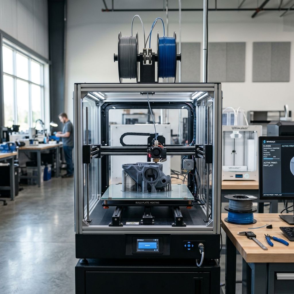
The Industrial Maker is reader-supported. When you purchase equipment, parts, or materials through links on our site, we may earn an affiliate commission at no additional cost to you.
Bambu Lab P1S & P1P Hardware Failure Diagnosis and Workshop Remediation
Field engineering analysis of thermal creep, extruder drive wear, umbilical harness fatigue, and kinematic degradation in high-cycle production environments.
Recommended Hardware: Bambu Lab P1S & P1P
Check current stock, real-time pricing, and official replacement parts directly on Amazon:
View on Amazon • Check Live Price →Engineering Root-Cause Summary
While the Bambu Lab P1P and P1S platforms have democratized high-speed CoreXY printing, continuous shop-floor operation reveals distinct mechanical, thermal, and electrical fatigue thresholds. The combination of closed-loop accelerations reaching 20,000 mm/s², compact toolhead packaging, and thermal confinement inside enclosed P1S volumes accelerates component failure across four specific sub-assemblies: drive gear teeth, cold-side heatbreak conduction paths, umbilical flex wires, and chassis-floor timing loops. When diagnosing intermittent print aborts or layer stepping, reference our interactive 3D Printer Troubleshooting diagnostic tool to cross-reference sensor codes before initiating toolhead teardowns.
1. Extruder Drive Failure & Thermal Creep Mechanics
The standard extruder assembly in the P1P and early P1S builds relies on stainless steel helical drive gears mated to a compact planetary reduction gearbox. Under workshop duty exceeding 800 print hours—particularly when running abrasive mineral-filled materials or running low-Tg polymers in closed enclosures—this assembly experiences severe mechanical abrasion and thermal softening.
Unlike the hardened tool-steel gears standard on the enterprise-tier Bambu Lab X1-Carbon & X1E, the factory P1P/P1S stainless drive gears wear rapidly when exposed to carbon-fiber or glow-in-the-dark filaments. The abrasive particulate acts as a lapping compound against the tooth root, reducing the effective pitch diameter and opening the tooth clearance from the nominal 0.15 mm to over 0.42 mm. This slop manifests as intermittent micro-slippage during rapid retract-unretract cycles, causing sudden volumetric underextrusion that operators frequently misidentify as partial nozzle blockages.
Thermal creep represents an even more common shop failure mode on the P1S. When operating inside an enclosed chamber without ventilation, ambient internal air temperatures routinely reach 46°C to 52°C during extended PLA or PETG prints. Standard polylactic acid has a glass transition temperature () between 55°C and 60°C. Conductive heat transfer through the bimetallic heatbreak follows Fourier's Law of Thermal Conduction:
Where is the thermal conductivity of the heatbreak alloy ( for the 316L stainless sleeve), is the cross-sectional wall area (), and is the effective transition zone length (). Under continuous 220°C nozzle setpoints, the heat flux entering the cold heatsink is approximately 2.54 Watts.
The miniature 3010 axial cooling fan on the toolhead delivers roughly 3.8 to 4.2 CFM of static airflow at 100% duty cycle. As static chamber air temperature () rises above 45°C, the convective heat transfer coefficient diminishes significantly because the temperature differential narrows. When heatsink temperature crosses 52°C, filament residing in the cold zone begins bulk viscoelastic deformation:
Under a mechanical feeder drive force , the softened filament mushrooms radially inside the PTFE transition sleeve from its nominal 1.75 mm diameter to over 2.05 mm, exceeding the internal barrel clearance and creating an unrecoverable mechanical lockup.
2. Toolhead Umbilical Flexure & Signal Fatigue
The P1-series umbilical harness routes DC power, high-speed SPI/I2C communication buses, and thermistor signal lines through an articulated cable chain or supported nylon sleeve that oscillates across a 256 mm travel span at speeds up to 500 mm/s. The localized bend radius at the toolhead entry gland measures approximately 28 mm, well below the industrial standard bend radius () recommended for high-flex robotic wiring.
After roughly 1.2 to 1.8 million motion cycles, internal copper strand fatigue occurs along the high-gage conductors feeding the Toolhead (TH) interface board. This fatigue typically manifests as intermittent open-circuit faults that only trigger during extreme high-speed travel strokes toward the front-right gantry corner. The machine controller triggers error code HMS_0300_0100_0001_0004: "The toolhead communication is abnormal".
Technicians often waste hours swapping hotend assemblies or cleaning connector pins when the actual breakdown is copper conductor necking inside the continuous-flex jacket. To verify umbilical integrity without teardown, hook up a digital multimeter in continuity latch mode across pins 3 and 4 of the main interface harness while manually traversing the printhead along its diagonal stroke. Any transient resistance spike above 1.2 Ohms confirms structural conductor shear requiring harness replacement.
3. Mainboard (MC) Cooling Fan Burnout & Stepper Throttling
On early production batches of the P1P, the mainboard cooling fan was omitted entirely or operated as a passive passive-flow setup. On the P1S, a 4010 radial blower provides forced air over the integrated Texas Instruments TMC-derived stepper motor drivers soldered directly to the main PCB. In high-particulate farm environments, this blower accumulates airborne plasticizer vapors and fine dust, leading to bearing seizure.
When the MC fan fails, thermal dissipation from the XY CoreXY stepper drivers relies solely on the small stamped aluminum heatsinks. Once driver junction temperature exceeds 135°C, the internal thermal protection circuitry initiates current clipping:
This dynamic current reduction lowers holding torque on the dual 42-48 stepper motors by 30% to 55%. Under rapid directional vector changes at 20,000 mm/s² acceleration, available mechanical torque falls below the inertial resistance of the toolhead assembly (), causing skipped steps along the 45-degree CoreXY axis. The user notices progressive layer shifts that compound every 20-30 minutes, without any foreign debris obstructing the carbon fiber gantry rods.
4. Triple Z-Axis Lead Screw Desynchronization
The build platform on the P1S/P1P is cantilevered on three lead screws coupled by a single continuous closed-loop GT2 timing belt routed beneath the bottom sheet-metal chassis. Tension on this 1200 mm timing loop is maintained by a spring-loaded idler pulley mounted to a stamped steel bracket.
Under workshop continuous operation, three distinct degradation mechanisms affect bed leveling and Z-axis accuracy:
First, downward bed vibration during rapid Z-hops transfers cyclic axial loads to the lead screw thrust bearings. Second, belt tooth elastomeric creep expands overall belt circumference by 0.3% to 0.5% over 1,500 hours, causing the spring tensioner to reach the end of its travel slot. Third, the factory idler bracket pivot accumulates micro-slop, permitting the idler pulley to cant at an angle of 1.5° to 2.5° relative to the belt plane.
When belt tension drops below 28 Hz (measured via acoustic frequency tuning), high-acceleration descent movements cause the rear lead screw pulley to skip 1 to 2 teeth relative to the front twin screws. Because the machine lacks independent Z-stepper drivers for each screw, automatic bed leveling cannot mechanically compensate for a physically tilted build platform beyond ±1.2 mm without severe lead screw binding and brass nut gouging.
Comprehensive Diagnostic & Verification Matrix
When systematic hardware anomalies arise on the P1S or P1P, use this diagnostic matrix to isolate the mechanical or electrical root cause prior to component disposal:
| Failure Symptom | Root Mechanism | Physical Verification Test | Workshop Remediation Protocol |
|---|---|---|---|
| Intermittent underextrusion after 40 min | Cold-end heat creep; PLA filament deformation past 52°C | Check heatsink exit temperature with IR probe; inspect pulled filament for bulb diameter > 1.95 mm | Crack top glass lid 20 mm; install hardened steel gears; replace 3010 cold-end fan |
| HMS 0300-0100-0001-0004 Communication Loss | Cyclic copper fatigue in toolhead umbilical flex ribbon | Wiggle test at toolhead entry gland with multimeter continuity tone enabled | Replace umbilical harness; install reinforced strain-relief gland with 45 mm bend radius |
| Compounding 45-degree diagonal layer shifts | MC board fan stall triggering stepper driver thermal throttling | Check MC fan RPM via developer console; measure driver heatsink temp (> 110°C) | Replace 4010 24V MC fan; clean dust buildup from driver heatsink fins; re-seat thermal pads |
| Bed tramming failure; Z-axis binding squeal | Under-chassis GT2 loop tooth skip; idler bracket deflection | Measure mechanical gap at all 3 lead screw collar points using digital depth calipers | Invert chassis, loosen idler tensioner, mechanically lock lead screws with printable jigs, re-tension belt to 35 Hz |
| Excessive XY ghosting and ringing at >250 mm/s | Carbon rod resin buildup; idler pulley bearing race fretting | Clean rods with 99% IPA; rotate XY passive idlers by hand checking for notched rotation | Degrease carbon rods with pure IPA; replace rear gantry idlers with sealed ABEC-5 flange bearings |
Workshop Overhaul Protocol: Step-by-Step Diagnostic Checklist
When returning a high-cycle P1S or P1P to factory mechanical tolerances, follow this methodical maintenance and overhaul protocol:
- Extruder Teardown & Hardened Upgrade: Disconnect hotend heater and thermistor. Remove the two M3 socket head cap screws securing the extruder housing. Strip down the planetary gears, degrease the needle roller bearings, inspect the stainless drive teeth under 10x magnification, and install hardened tool-steel gears (58-62 HRC) lubricated exclusively with PTFE-infused synthetic grease.
- Hotend Fan Flow & Cold Block Verification: Measure the 3010 fan current draw (nominal 0.08A at 5V). Clear plastic stringing and dust from the heat sink cooling fins using 6 bar dry compressed air. Re-seat the ceramic heater element and thermistor using boron nitride thermal paste rated for 1000°C; torque mounting screws to 0.35 Nm.
- Umbilical Harness & Strain Relief Retrofit: Inspect the toolhead entry harness for outer jacket abrasion. Solder or crimp high-flex silicone-insulated wire if localized patching is required, or install an OEM replacement. Mount an aftermarket semi-rigid PETG cable guide to prevent localized pinch points at maximum X travel.
- Under-Chassis GT2 Belt Re-Synchronization: Rest the printer on its back on a protective foam pad. Remove the 10 bottom sheet-metal screws. Place three identical precision 100.00 mm gauge blocks between the bed carriage frame and the bottom chassis. Loosen the spring idler lock screw, equalize lead screw timing manually by rotating the belt pulleys until all three corners seat flush against the gauge blocks, then tighten the idler screw to 0.6 Nm.
- Carbon Rod Decontamination: Never apply grease, oil, or WD-40 to the carbon fiber X-axis guide rails. Saturate a lint-free microfiber cloth with 99.9% isopropyl alcohol and wipe the rods down repeatedly until no black graphite residue or hardened dust appears on the cloth. Cycle the toolhead across full stroke 10 times to expel debris from the self-lubricating polymer bushings.
Frequently Asked Questions
Why does my Bambu P1S extruder click and jam exclusively when printing PLA?
Chamber air temperatures exceeding 45°C inside an enclosed P1S soften PLA before it enters the melt zone, causing drive gear flattening and severe cold-end heat creep; keep the front glass door cracked open or remove the top glass lid during PLA runs.
How do I identify whether a toolhead error code is caused by the TH board or the cable?
Perform an active continuity sweep with a multimeter across the umbilical harness while physically bending the cable at the toolhead entrance gland; intermittent open-circuit beeps verify copper fatigue in the wiring harness rather than a defective TH motherboard.
What causes the P1P to lose bed tramming across long multi-day production runs?
The under-chassis GT2 synchronization belt loses tension over time as the stamped sheet-metal idler bracket flexes, allowing belt teeth to skip on the rear lead screw pulley during rapid Z-hop descents.
Can I lubricate the carbon fiber rods on the Bambu P1S to eliminate bearing squeaks?
No, the carbon fiber rails utilize self-lubricating engineered polymer bushings; applying oils or grease will attract abrasive airborne particles, degrade the carbon resin matrix, and cause permanent gantry binding.
Critical Shop Protocol: High-Voltage Bus & Toolhead Torquing
Always isolate the AC power cable and allow the switched-mode power supply capacitors to discharge for at least 180 seconds before opening the bottom chassis or servicing the MC controller. When reinstalling the hotend ceramic heater screws into the aluminum heatsink, limit tightening torque strictly to 0.35 Nm; overtightening stripped M2 threads into soft cast aluminum will permanently destroy heat dissipation coupling and mandate full toolhead replacement.
Related Intel
Bambu Lab P1S & P1P Common Problems: Workshop Fixes
Comprehensive engineering root-cause analysis and troubleshooting guide for Bambu Lab P1S and P1P 3D printers. Addresses high-incidence workshop failures including AMS PTFE capstan friction binding, extruder filament cutter jamming, carbon rod bearing slurry build-up, toolhead cover detachment, and enclosure heat creep clogs. Features mathematical formulations for Euler-Eytelwein capstan tube friction and CoreXY belt harmonic resonance tuning, backed by actionable maintenance procedures and diagnostic matrices.
Best Materials for Creality K2 Pro & K1C: Industrial Filament Guide
Definitive materials selection and thermal processing guide for the Creality K2 Pro and K1C high-speed CoreXY 3D printers. Evaluates fiber-reinforced polymers (PA-CF, PET-CF, PC-CF), engineering thermoplastics (ASA, ABS, Polycarbonate), and high-flow flexibles. Includes mathematical formulations for thermal shrinkage strain, peel moment crystallization stress, and hotend volumetric throughput ceilings. Features comprehensive rheological parameter tables, hygroscopic pre-drying protocols, and enclosure heat management guardrails for zero-delamination industrial manufacturing.
Bambu Lab P1S vs P1P: Slicer & Hardware Comparison
Head-to-head engineering and software evaluation of the Bambu Lab P1S versus P1P CoreXY 3D printers. Analyzes enclosure thermal equilibrium thermodynamics, MC board auxiliary cooling, high-temperature composite processing (ABS, ASA, PA-CF), and software ecosystem differences across Bambu Studio, OrcaSlicer, and PrusaSlicer. Features an exhaustive workshop ROI model, failure rate metrics, and a definitive procurement verdict for commercial prototyping shops.