Prusa XL Multi-Tool Problems and Workshop Fixes

* Affiliate Disclosure: We may earn a commission from qualifying purchases made via our verified links at no additional cost to you.
The Industrial Maker is reader-supported. When you purchase equipment, parts, or materials through links on our site, we may earn an affiliate commission at no additional cost to you.
Prusa XL Multi-Tool Calibration and Kinematic Docking Fixes
Field diagnosis of kinematic pin wear, segmented bed thermal drift, and CoreXY belt resonance across continuous production shifts.
Recommended Hardware: Prusa XL (Multi-Tool)
Check current stock, real-time pricing, and official replacement parts directly on Amazon:
View on Amazon • Check Live Price →Engineering Diagnostic Summary
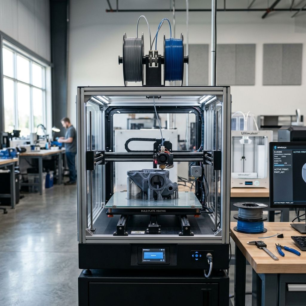
The Prusa XL multi-tool system replaces material-wasting purge towers with an active mechanical toolchanger based on a Maxwell kinematic ball-and-groove coupling. While this architecture provides significant material savings in multi-color and multi-material engineering prints, the mechanical handover introduces physical repeatability limits, micro-switch registration tolerances, and differential thermal expansion between parked and active toolheads. On workshop floors running multi-day cycles, layer-to-layer XY registration shifts and toolhead drops originate from three primary mechanical issues: kinematic pin surface fretting, CoreXY belt tension asymmetry degrading carriage squareness, and loadcell tare drift on individual bed tiles. Use our 3D Printer Troubleshooting tool to verify whether motion errors originate from mechanical backlash or resonance compensation profiles before adjusting hardware tensioners.
Kinematic Handover Mechanics and Coupling Tolerances
Every tool change sequence on the Prusa XL relies on kinematic repeatability governed by three hardened steel locating dowels that seat directly into matching semi-cylindrical grooves machined into each toolhead carriage plate. Under clean workshop conditions, a true Maxwell kinematic mount provides spatial repeatability below 5 microns. However, after several hundred production hours in typical manufacturing environments, ambient airborne dust, vaporized plasticizers, and microscopic debris settle onto these precision contact surfaces, altering the physical friction coefficient.
The toolchanger latch mechanism employs an active stepper-driven servo cam that pulls the selected Nextruder firmly against the carriage dock. If the mating contact pads accumulate dry lubricant residues or foreign particles, the toolhead cannot seat completely flush against its mechanical reference plane. While the carriage optical sensor may still acknowledge tool presence, an angular tilt of merely 15 microns at the kinematic interface translates into noticeable color-bleed seams and surface steps on dual-material boundary perimeters. In worse situations, when dynamic acceleration exceeds 8,000 mm/s² during rapid non-print transit moves, an incompletely seated latch slips off its detent, causing a toolhead drop that triggers an emergency halt.
- Kinematic Pin Tolerances: Hardened chrome steel pins, target seating runout under 0.005 mm
- Cam Latch Holding Force: 14.5 N static spring preload against the tool carriage chassis
- Dock Clearance Gap: 0.8 mm nominal separation between dock arm forks and the tool carriage
- Tool Swap Cycle Latency: 4.8 seconds average per swap cycle at 250 mm/s transit speed
- Micro-Switch Actuation: 0.4 mm mechanical travel with 0.08 mm optical sensor hysteresis
- Repeatability Standard: Sub-0.01 mm positional variance across 500 consecutive tool swaps
Physics of Kinematic Seating and Inertial Forces
Understanding toolchanger reliability requires analyzing the mechanical forces acting on the toolhead during dynamic acceleration. The toolhead assembly on each Nextruder carriage has a finished mass of approximately 340 grams (0.340 kg). During rapid repositioning moves across the 360 mm span, the CoreXY motion system accelerates the toolhead up to 15 m/s² (approximately 1.53 G).
The inertial force attempting to unseat the toolhead from its kinematic grooves during peak directional change is calculated by Newton's second law:
Substituting the physical values from the shop floor:
To keep the kinematic pins firmly seated in their V-grooves without micro-shifting or chatter under dynamic reversals, the cam latch mechanism must provide a normal holding force that comfortably exceeds this inertial threshold after accounting for the friction coefficient between lubricated ground steel surfaces:
Where represents the contact angle of the V-groove walls and represents boundary lubrication conditions. If the cam tension spring weakens or the latch lever accumulates friction due to dry pivots, the available retention force drops below the required 12 N threshold. When this occurs, high-speed directional changes cause the toolhead to rock slightly within the kinematic cups, manifesting as intermittent horizontal banding on parts printed with that specific tool.
Thermal Expansion Drift Across Multi-Head Assemblies
Thermal equilibrium is one of the most critical yet frequently ignored variables in multi-tool FDM operations. In multi-material production—for example, printing structural copolyester (PETG) alongside soluble support materials like BVOH or PVA—idle toolheads park at lower standby temperatures (typically 70°C to 110°C) to prevent polymer charring, oozing, and heat creep inside the heatbreak. When Tool 2 is summoned by the gcode, its heater cartridge rapidly ramps to its active printing temperature of 240°C.
This rapid thermal swing induces significant linear thermal expansion along both the vertical Z-axis and horizontal XY mounting planes. The structural distance from the kinematic reference pins down to the nozzle orifice measures approximately 65 mm, comprising the aluminum heatsink body, the titanium heatbreak tube, and the brass or hardened steel nozzle body:
Where:
Calculating the overall elongation:
Even when moving from an idle standby temperature of 100°C to an operating temperature of 240°C (), the physical length of the hotend changes by nearly 195 microns. If a print job deposits an initial layer immediately after tool pickup without allowing the hotend assembly to reach steady-state thermal expansion, the nozzle will sit noticeably closer to the print bed than its calibrated offset predicts. This discrepancy produces severe first-layer scarring or surface gouging. Similar thermal expansion phenomena affect single-tool printers, as analyzed in our review of the Prusa MK4S frame rigidity and extruder performance, where unsoaked heating blocks distort baseline bed mesh calibrations.
Segmented Bed Thermal Warping and Loadcell Tare Drift
To eliminate the spherical bowing inherent in massive 360 x 360 mm single-piece cast aluminum heatbeds, the Prusa XL incorporates a segmented array of 16 individual 4x4 heated PCB tiles. Each tile floats on dedicated expansion standoffs to accommodate lateral thermal expansion independently. While this modular design successfully prevents global bed warping, it introduces subtle localized temperature steps and mechanical compliance variations across tile interfaces.
Each tile is separated by an expansion gap of approximately 1.2 mm. At bed temperatures above 85°C (standard for PETG, ABS, and Polycarbonate), the center of each tile expands slightly upward relative to its clamped edges, producing micro-undulations of 20 to 35 microns across the build area. Furthermore, the Nextruder loadcell system uses the nozzle itself as a physical contact probe, eliminating mechanical microswitches and inductive probes. However, this loadcell system is vulnerable to tare drift under two specific conditions:
- Nozzle Plastic Crust: Semi-solidified filament remnants on the nozzle tip exert early mechanical contact force (15 to 30 grams) before the metal tip touches the spring sheet, offsetting bed height calculations.
- PCB Standoff Binding: Over-tightened mounting screws prevent individual tile expansion, causing the tile corners to tilt upward under sustained thermal soak.
- Ground Loop Voltage Fluctuations: Inadequately grounded spring steel sheets introduce electrical noise into the strain gauge analog-to-digital circuitry during mesh leveling.
- Cold Bed Probing Errors: Probing the bed while cold and printing hot produces dimensional errors due to expansion in the steel sheet alignment pins.
CoreXY Gantry Belt Tension Imbalance and Orthogonality
The Prusa XL motion system uses a classic CoreXY arrangement driven by two long 9 mm synchronous belts reinforced with internal fiberglass cords. Because the gantry must span a 360 mm x 360 mm physical build envelope, each belt loop exceeds two meters in total linear length. Consequently, the gantry is exceptionally sensitive to differential tension between the two driving belt circuits.
If Belt A is tensioned to 92 Hz while Belt B sits at 78 Hz, the gantry crossbar loses true orthogonality during rapid diagonal movements. Under continuous high-speed infill patterns, circular geometry distorts into subtle ellipses with major-to-minor axis errors exceeding 0.12 mm. More critically, an out-of-square gantry misaligns the tool carriage relative to the rear-mounted tool docks. When the carriage travels backward to park Tool 3, the pickup fingers approach the dock pocket at a slight yaw angle. This forces the dock forks to flex laterally, accelerating plastic wear on the dock fingers and causing the carriage cam to bind during pickup cycles.
| Failure Mode | Underlying Mechanical Cause | Diagnostic Threshold | Corrective Shop Procedure |
|---|---|---|---|
| Toolhead Drop During Travel | Fretting wear on kinematic dowels / Slack cam belt | >0.06 mm lateral deflection under 5 N force | Clean pins with 99% IPA; apply micro-film Krytox; tension cam belt to 65 Hz |
| Multi-Material XY Layer Step | Asymmetric belt tension / Thermal soak discrepancy | >8 Hz frequency difference between Belts A and B | Acoustically tune CoreXY belts to 85 Hz +/- 2 Hz using frequency meter |
| Inconsistent First Layer Height | Contaminated nozzle tip during loadcell zeroing | Loadcell baseline drift > 12 g before bed touch | Program nozzle wipe cycle at 160C prior to bed probing routines |
| High-Speed Ghosting & Ringing | Idler bearing play / Input shaper frequency drift | Visible ripples at 2 mm belt tooth pitch | Re-torque M3 idler mounting screws to 1.4 Nm; re-run onboard accelerometer calibration |
| Outer Tool Underextrusion (T4/T5) | Reverse Bowden drag through side feed path | Filament pull force exceeding 3.2 N at extruder inlet | Increase PTFE tube bend radii; install low-friction ball bearing spool rollers |
Extruder Drive and Reverse Bowden Friction on Outer Heads
The Nextruder assembly features a precision 1:10 planetary gearbox coupled to large-diameter dual drive gears. This setup delivers immense grip without crushing soft filaments. However, in full five-tool configurations, Tools 4 and 5 require extended PTFE guide tubes running from the side-mounted spool holders to the toolhead parking docks. On long travel moves toward the far front corner of the build volume, these tubes experience sharp bending radii.
When extruding abrasive composite materials such as carbon-fiber reinforced nylon (PA12-CF), the abrasive filament acts like a flexible wire saw, cutting microscopic grooves into the inner wall of standard 4 mm OD / 2.5 mm ID PTFE tubing. Over several kilograms of throughput, internal friction increases drastically, requiring more than 4 N of pulling force from the extruder stepper. This resistance causes intermittent step skipping, which shop operators often mistake for a hotend clog. When servicing the planetary gear drive, technicians should review standard workshop disassembly practices such as those outlined in our guide on replacing Prusa MK4/S extruder assemblies to verify gear mesh backlash and idler preload before replacing stepper motors.
Step-by-Step Workshop Calibration Protocol
To eliminate toolchanger dropouts and maintain precise multi-material alignment across extended production runs, execute the following calibration workflow sequentially:
- Step 1 - Structural Squaring: Power off the printer. Disengage the CoreXY stepper motor belts. Manually slide the gantry carriage firmly against the front frame hard stops. Verify that both left and right carriage brackets touch their respective mechanical stops simultaneously without twisting the crossbeam.
- Step 2 - Acoustic Belt Tuning: Suspend a smartphone or acoustic frequency meter 10 mm above the center span of each belt loop. Pluck the belt cleanly. Adjust the tensioning bolts on the rear stepper mounts until both Belt A and Belt B resonate between 84 Hz and 86 Hz.
- Step 3 - Kinematic Contact Dressing: Thoroughly clean all three locating dowels and the mating carriage V-grooves on each toolhead using 99% isopropyl alcohol and lint-free swabs. Inspect surfaces under magnification for fretting burrs. Apply an ultra-thin film of dry PTFE lubricant, wiping off any visible wet buildup.
- Step 4 - Tool Dock Alignment: Loosen the dock arm mounting screws along the rear aluminum extrusion. Insert the factory alignment gauge into the tool dock. Ensure that the pickup pins slide effortlessly into the dock fingers with zero vertical lifting or lateral binding. Torque all dock hardware to 2.2 Nm.
- Step 5 - Thermal Pre-Soak and Calibration: Power on the printer. Heat all 16 bed tiles to 80°C and all active hotends to 150°C. Allow the entire frame to heat-soak for 25 minutes. Once thermally stabilized, execute the optical tool offset calibration followed by full loadcell mesh bed leveling.
Long-Term Preventive Maintenance Cycles for Multi-Tool Setups
Running a five-tool Prusa XL in a production environment requires structured preventive maintenance. Operating multiple toolheads multiplies the number of moving parts, wear points, and electronic interconnects by five. To prevent unexpected failures during 48-hour prints, follow this maintenance schedule based on actual machine hours:
- Every 150 Operating Hours: Inspect kinematic locating pins for fretting dust. Clean with alcohol and re-apply dry lubricant. Check toolchanger cam latch belt tension.
- Every 300 Operating Hours: Verify CoreXY belt resonance frequencies using an acoustic meter. Re-torque gantry idler pulley screws to 1.4 Nm. Inspect reverse Bowden tubes for internal grooving.
- Every 600 Operating Hours: Disassemble Nextruder planetary gearboxes. Clean old grease, inspect brass sun gear teeth for pitting, and repack gears with synthetic PTFE grease.
- Every 1200 Operating Hours: Replace the flexible toolhead umbilical ribbon cables on high-cycle tools. Constant flexing across the toolchanger travel arc causes fatigue micro-fractures in copper traces.
- Every 2000 Operating Hours: Replace linear rail carriage ball bearings or repack rail blocks with synthetic grease. Inspect segmented bed expansion standoffs for thermal galling.
Frequently Asked Questions
Why does the Prusa XL drop toolheads during rapid non-print moves?
Tool drops occur when the carriage latch cam belt loses tension or debris coats the kinematic pins, preventing the spring-loaded latch from completing its mechanical over-center lock.
How do I correct positional XY offsets between two different nozzles?
Run the optical tool offset calibration routine only after pre-soaking the bed and hotends at operating temperatures for 25 minutes to eliminate thermal expansion variance.
What causes the Nextruder loadcell to produce inconsistent first layer heights?
Hardened filament residue on the nozzle tip makes premature contact with the build sheet, introducing a false tare offset into the strain gauge measurement circuit.
What frequency should the Prusa XL CoreXY belts be tuned to?
Both CoreXY belts should be tuned acoustically to 85 Hz (+/- 2 Hz) across a 150 mm measuring span to ensure gantry squareness and prevent tool dock binding.
Workshop Safety and Equipment Protection Protocol
Never place hands, inspection tools, or cleaning swabs inside the build chamber while toolchanger operations are underway. The high-speed CoreXY gantry and active tool docking mechanisms generate severe pinch hazards with sufficient torque to cause finger injuries or snap aluminum tool mounts. Always power down the machine before inspecting tool docks, and verify that all 16 bed tile temperature sensors report plausible room-temperature values before energizing high-current bed heaters to guard against thermal runaway risks caused by damaged wiring harnesses.
Related Intel
Bambu Lab P1S & P1P Common Problems: Workshop Fixes
Comprehensive engineering root-cause analysis and troubleshooting guide for Bambu Lab P1S and P1P 3D printers. Addresses high-incidence workshop failures including AMS PTFE capstan friction binding, extruder filament cutter jamming, carbon rod bearing slurry build-up, toolhead cover detachment, and enclosure heat creep clogs. Features mathematical formulations for Euler-Eytelwein capstan tube friction and CoreXY belt harmonic resonance tuning, backed by actionable maintenance procedures and diagnostic matrices.
Best Materials for Creality K2 Pro & K1C: Industrial Filament Guide
Definitive materials selection and thermal processing guide for the Creality K2 Pro and K1C high-speed CoreXY 3D printers. Evaluates fiber-reinforced polymers (PA-CF, PET-CF, PC-CF), engineering thermoplastics (ASA, ABS, Polycarbonate), and high-flow flexibles. Includes mathematical formulations for thermal shrinkage strain, peel moment crystallization stress, and hotend volumetric throughput ceilings. Features comprehensive rheological parameter tables, hygroscopic pre-drying protocols, and enclosure heat management guardrails for zero-delamination industrial manufacturing.
Bambu Lab P1S vs P1P: Slicer & Hardware Comparison
Head-to-head engineering and software evaluation of the Bambu Lab P1S versus P1P CoreXY 3D printers. Analyzes enclosure thermal equilibrium thermodynamics, MC board auxiliary cooling, high-temperature composite processing (ABS, ASA, PA-CF), and software ecosystem differences across Bambu Studio, OrcaSlicer, and PrusaSlicer. Features an exhaustive workshop ROI model, failure rate metrics, and a definitive procurement verdict for commercial prototyping shops.