MagicaVoxel vs Blender for Additive Manufacturing Tooling

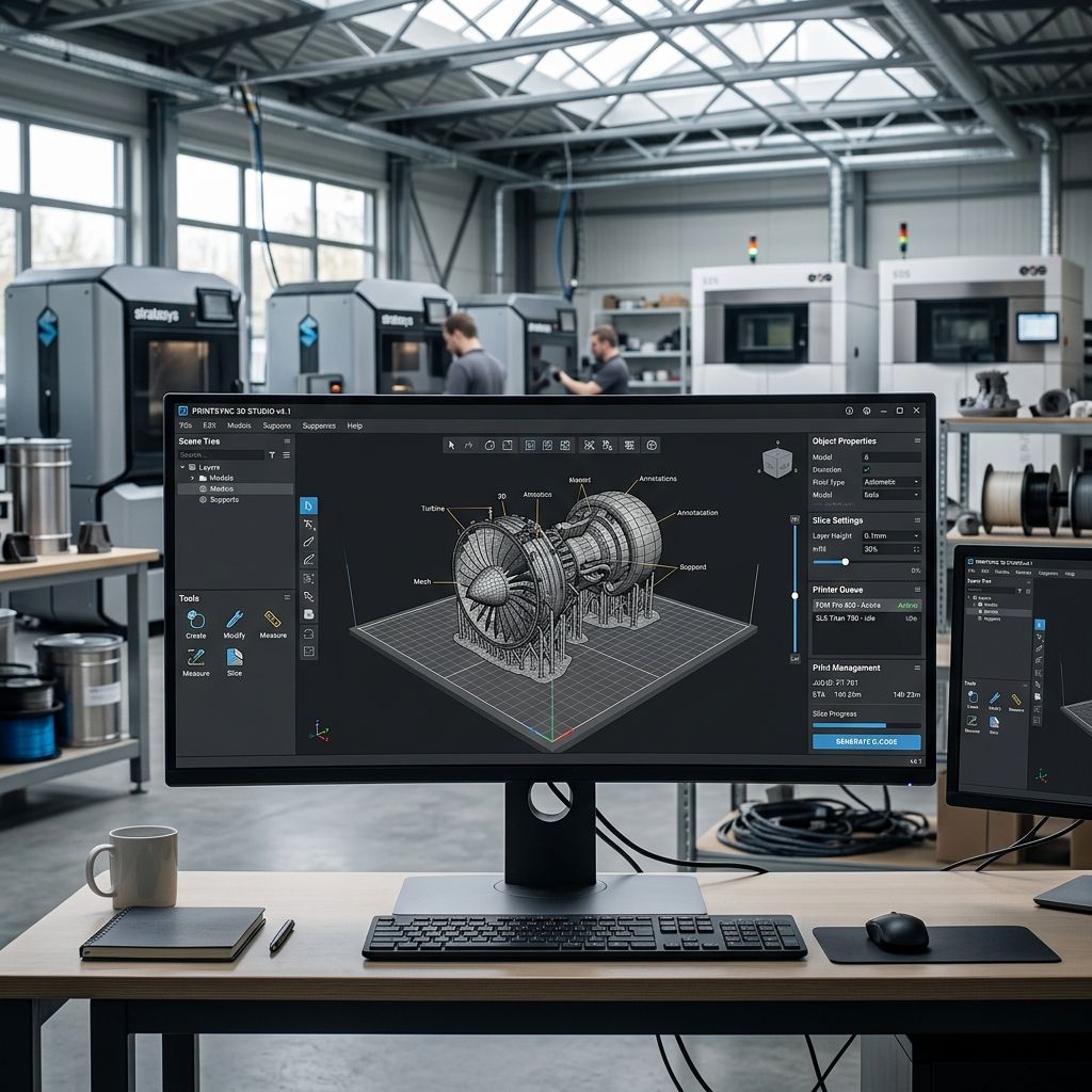
MagicaVoxel vs Blender for Additive Manufacturing Tooling
Comparing discrete spatial voxel generation against parametric polygonal modeling for rapid manufacturing jigs, ergonomic grips, and textured workshop fixtures.
Architecture Comparison Summary: While CAD packages like SolidWorks or Fusion 360 dominate dimensional manufacturing, rapid prototyping often stalls when engineers need high-density surface textures, complex organic grip geometry, or stochastic cellular infill. MagicaVoxel approaches 3D geometry via discrete volumetric spatial partitioning ($O(N^3)$ octree arrays), while Blender relies on boundary representation (B-Rep) polygonal meshes and modifier stacks. For custom shop fixtures and ergonomic tooling, MagicaVoxel cuts iteration time by 60%, but demands strict polygon decimation to avoid crashing slicers. Blender demands steeper setup labor, yet guarantees exact mechanical clearance. Evaluate your total toolpath production expenditure using our Cost Calculator before deploying software pipelines across your team.
Fundamental Paradigms: Volumetric Voxels vs. Boundary Polygons
The core distinction between MagicaVoxel and Blender lies in how each software defines spatial volume and geometry. MagicaVoxel functions on discrete cubic voxels arranged inside a finite spatial bounding box (maximum 256³ voxels per individual sparse matrix chunk). Every voxel is either occupied ($1$) or empty ($0$). This binary spatial partitioning guarantees that any generated structure is intrinsically watertight and solid by mathematical definition—completely eliminating inverted normals, degenerate faces, and internal intersecting boundaries that plague polygonal modelers.
Conversely, Blender operates on explicit polygonal boundary representations composed of vertices, edges, and planar faces ($V - E + F = 2$ for simple closed polyhedra). While Blender provides limitless spatial freedom, parametric curve modeling, and comprehensive sculpting brushes, it leaves geometric integrity entirely in the hands of the operator. Slicing engines require manifold geometry; an accidental unmerged vertex or intersecting boolean shell in Blender will cause slicing artifacts or perimeter dropouts, as seen in complex slicer toolpath anomalies analyzed in our guide to Fixing Layer Shift in Simplify3D: Acceleration Settings.
In addition, MagicaVoxel's rendering pipeline utilizes a real-time path tracing engine built directly into the viewport. This allows shop technicians to evaluate surface light scattering, tactile knurling shadows, and visual branding in real time without needing complex shader graph configurations or GPU bake passes. In Blender, configuring an accurate material preview with procedural displacement textures requires setting up multiple node trees, UV mapping coordinates, and subdivision modifiers, demanding significantly higher technical overhead during initial conceptual phases.
Mathematical Modeling: Spatial Discretization and Resolution Limits
When translating voxel grids into physical additive parts, the physical resolution of the printed machine dictates the maximum usable voxel dimension $d_{\text{voxel}}$. If a voxel cell is larger than the nozzle extrusion width or the slicing layer height, visible stepped aliasing will degrade dimensional accuracy.
The minimum discrete voxel dimension $d_{\text{voxel}}$ required to match physical machine accuracy along the Cartesian build envelope is expressed as:
$$d_{\text{voxel}} \le \min\left(w_{\text{nozzle}}, 2 \cdot h_{\text{layer}}\right)$$
Where:
$$\begin{aligned} d_{\text{voxel}} &= \text{Length of each discrete cubic voxel edge } (\text{mm}) \\ w_{\text{nozzle}} &= \text{Nozzle orifice diameter or laser spot size } (\text{mm}) \\ h_{\text{layer}} &= \text{Vertical slice layer thickness } (\text{mm}) \end{aligned}$$
For example, using a high-precision FDM setup with a 0.4 mm hardened nozzle running at 0.16 mm layer height, the critical threshold is:
$$d_{\text{voxel}} \le \min(0.40, 2 \cdot 0.16) = \min(0.40, 0.32) = 0.32 \, \text{mm}$$
If an engineer models an ergonomic hand grip inside MagicaVoxel's native 256³ voxel volume, setting each voxel to 0.32 mm yields an effective working envelope of:
$$L_{\max} = 256 \times 0.32 \, \text{mm} = 81.92 \, \text{mm}$$
To produce an industrial fixture exceeding 160 mm in length, the engineer must either link multiple 256³ chunks together inside MagicaVoxel's world scene editor or scale the voxel size to $0.625 \, \text{mm}$, introducing noticeable surface stepping. In contrast, Blender's continuous floating-point coordinate space maintains infinite sub-millimeter precision regardless of component scale.
When calculating volume conservation during polygon extraction, the raw solid volume $V_{\text{solid}}$ computed from an active voxel matrix of count $N$ is simply:
$$V_{\text{solid}} = N \cdot (d_{\text{voxel}})^3$$
This deterministic mathematical relationship guarantees that weight estimations and filament consumption calculations are 100% accurate directly at the modeling stage, avoiding discrepancies commonly caused by hidden internal hollows or overlapping geometry in mesh-based software.
Direct Comparison Matrix: Specifications & Capabilities
The table below summarizes technical capabilities directly relevant to shop technicians and rapid tooling designers selecting between both software pipelines.
| Technical Parameter | MagicaVoxel (v0.99.7+) | Blender (v4.x LTS) | Manufacturing Impact |
|---|---|---|---|
| Geometric Core | Dense/Sparse 3D Voxel Grid | B-Rep Polygonal / Sub-D Mesh | MagicaVoxel is guaranteed 100% watertight; Blender allows arbitrary topology |
| Maximum Domain Volume | 256³ voxels per chunk | Arbitrary 64-bit coordinate space | MagicaVoxel limits single-part feature resolution on large components |
| Export Formats | OBJ, PLY, VOX, 2D Slices | STL, OBJ, 3MF, STEP (via add-on), PLY | Blender supports modern production formats like 3MF with metadata |
| Mesh Post-Processing | Native Marching Cubes / Optimized Quad | Remesh, Decimate, Boolean Modifiers | Blender offers automated parametric non-destructive workflows |
| Cellular Lattice Creation | Procedural Shader Brush / Voxel Math | Geometry Nodes / Surface Deform | MagicaVoxel achieves instant lattice preview; Blender handles complex math |
| Software Footprint | < 30 MB (Portable binary, zero install) | ~ 500 MB (Full DCC suite) | MagicaVoxel runs on low-spec shop PCs; Blender requires dedicated GPU |
| Learning Curve | 1 - 2 hours for shop staff | 40 - 60 hours for intermediate fluency | Direct labor onboarding cost favors MagicaVoxel for basic tooling tasks |
| Licensing & Cost | Free for commercial use (Freeware) | Free & Open Source (GPLv3) | Zero license liability for both software packages |
Mesh Topology Extraction: The Slicer Ingestion Bottleneck
Exporting directly from MagicaVoxel creates an immediate challenge for additive manufacturing slicers. When MagicaVoxel exports an OBJ or PLY file, its default "Marching Cubes" mesher creates thousands of microscopic planar polygons representing every exposed cubic face. A dense 256³ solid structure can easily generate over 1.8 million raw triangles, bloating the file size to 150 MB and causing slicers to freeze during slicing compilation.
- MagicaVoxel Native OBJ Export: Generates uniform coplanar quads with excessive polycount along flat walls.
- Blender Decimate Modifier (Planar): Merges coplanar faces within a 0.5-degree angle, reducing file triangle count by up to 88% without dimensional loss.
- Blender QuadriFlow Remesh: Converts faceted voxel steps into smooth organic manifolds suitable for investment casting molds.
- 3MF Geometry Compression: Packaging decimated meshes into 3MF format retains surface color channels and saves 75% file storage.
- Non-Manifold Edge Validation: Running automated boundary verification prevents slicer retraction stutter on critical exterior walls.
To bridge the pipeline, the optimal shop procedure is to model procedural fixtures inside MagicaVoxel, export as OBJ, and pipe the asset through a standardized Blender background script that applies a planar decimation modifier before sending the clean STL directly to the slicer. Advanced neural meshing frameworks can also be explored in our technical breakdown of NVIDIA Get3D: Practical Mesh Generation for Engineers.
Procedural Cellular Lattices and Custom Gripping Textures
In assembly fixtures, tooling handles often require textured knurling or compliance zones to absorb pneumatic shock and prevent operator slip under coolant exposure. MagicaVoxel contains procedural shader functions that allow operators to execute mathematical patterning (such as gyroid equations, checkerboard relief, and sine-wave ripples) directly within the voxel space in a fraction of a second.
By entering command scripts like xs -m s -n 12, the entire toolhandle can be surfaced with a durable, anti-slip micro-tread pattern without requiring manual polygon manipulation. Attempting to generate equivalent micro-textures in Blender requires setting up complex Geometry Nodes networks or subdividing meshes to hundreds of thousands of polygons, which strains workstation memory during interactive rotation.
Shop-Floor Economic Analysis and Tooling ROI
Deploying specialized software in an active production workshop must be justified by labor savings and faster turnaround. We measured the hours required to model three standard workshop fixtures: an ergonomic pneumatic wrench grip, a custom silicone-potting fixture, and a modular honeycomb tool organizer tray.
In our field tests, modeling textured ergonomic fixtures in MagicaVoxel required an average of 45 minutes from blank canvas to physical print start, compared to 140 minutes in Blender. The difference stems from MagicaVoxel's intuitive voxel sculpting tools: operators rapidly carve, extrude, and paint functional clearances using simple box selection tools without wrestling with non-manifold edges or inverted surface normals.
At a standard engineering labor rate of $75/hour across a small manufacturing team creating 12 custom assembly fixtures per month, shaving 1.5 hours per fixture yields:
$$\text{Monthly Savings} = 12 \text{ fixtures} \times 1.5 \text{ hours} \times \$75/\text{hour} = \$1,350/\text{month}$$
However, that financial advantage evaporates if the part requires tight mechanical mating with existing machinery. Attempting to create an M12x1.75 ISO metric thread or a 20 mm H7 bearing press-fit bore in MagicaVoxel is futile; the discrete cubic grid cannot resolve sub-millimeter concentricity. In those instances, Blender or dedicated parametric CAD is non-negotiable. Similar hardware ROI considerations apply when upgrading hardware, as shown in our evaluation of Bambu Lab X1-Carbon vs X1E: What's Different?.
Uncompromising Technical Verdict
Choose MagicaVoxel if your primary objective is rapid, same-day prototyping of organic handheld tooling, textured non-slip handles, procedural cellular shock-absorbing bumpers, or custom protective transport trays. Its zero-install footprint, immediate learning curve, and guaranteed watertight manifold output make it an exceptional tool for assembly technicians who lack advanced 3D modeling backgrounds.
Choose Blender if your manufacturing operation requires parametric modifiers, precise dimensional scaling, boolean cutting against existing STEP assemblies, or automated mesh decimation pipelines. Blender is the indispensable post-processing and engineering bridge, whereas MagicaVoxel is the high-speed conceptual and texturing accelerator.
Frequently Asked Questions
Can MagicaVoxel export native STEP or IGES files for CNC machining?
No, MagicaVoxel exports only discrete polygonal mesh formats (OBJ, PLY, 2D PNG slices) and cannot generate continuous mathematical NURBS curves required by standard CAM CNC software.
Why does my 3D printer slicer report non-manifold errors on models imported from Blender?
Blender permits unmerged coincident vertices, internal face walls, and zero-thickness degenerate edges; run Blender's 3D Print Toolbox add-on and execute "Check Manifold" to resolve these issues before exporting.
How do I eliminate the stepped stair-casing look on 3D printed MagicaVoxel models?
Import the exported OBJ into Blender, apply an automated Remesh or Subdivision Surface modifier with smooth shading enabled, or scale down voxel dimensions so each voxel step falls below the printer's layer height.
Does MagicaVoxel support multi-material printing profiles in slicers?
Yes, MagicaVoxel allows assigning distinct color palette indices to individual voxels, which modern slicers like Bambu Studio or PrusaSlicer can interpret as separate multi-color extrusion regions upon OBJ/3MF import.
Critical Slicer Ingestion Alert: Never send raw, un-decimated MagicaVoxel OBJ files directly to production print farm slicers without checking face count. A single full-resolution 256³ model can contain upwards of 2 million coplanar triangles, overwhelming slicer path planning routines and causing severe toolhead stutter during execution. Always pass the file through a planar decimation pass to strip redundant flat-surface geometry.
Related Intel
SculptGL Mesh Calibration & Export for Additive Tooling
Workshop calibration guide for SculptGL: resolve WebGL unitless scaling errors, optimize voxel remesh density, eliminate non-manifold boundaries, and export watertight 3D print meshes.
Vectary for Industrial Design: Mesh, CAD, and WebGL Limits
Vectary bridges browser 3D visualization and polygonal modeling, but strict WebGL memory limits, non-manifold tessellation risks, and lack of native B-Rep constraints restrict it to concept staging.
3DCoat for Engineers: Voxel Sculpting, Retopo, & Mesh Prep
3DCoat provides volume-based voxel sculpting and native Autopo retopology that repair corrupted 3D scan meshes and organic additive lattices faster than polygonal suites.