3DCoat for Engineers: Voxel Sculpting, Retopo, & Mesh Prep

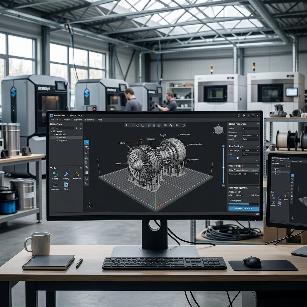
3DCoat for Engineers: Voxel Sculpting, Retopo, & Mesh Prep
While game artists view 3DCoat primarily as a digital sculpting and PBR texturing suite, reverse engineers and additive manufacturing job shops rely on its unique volumetric voxel core to repair broken scan meshes, hollow complex cast geometries, and generate production-ready quad topology.
Platform Overview: 3DCoat in Industrial Product Development
3DCoat differs fundamentally from traditional polygonal mesh modelers like Blender or subdivision packages like ZBrush. Its primary geometry workspace operates on volumetric pixels (voxels), storing geometry as a continuous 3D density field rather than an empty polygonal boundary shell. This allows engineers to perform complex booleans, hollowing operations, and wall-thickness adjustments without creating non-manifold self-intersections or inverted surface normals.
- Core Geometric Engine: Volumetric Voxels (Density Grids) + Surface Dynamic Tessellation
- Surface Extraction Protocol: Dual Marching Cubes with Adaptive Feature Edge Snapping
- Topology Reconstruction: Native 'Autopo' (Automated Quad Retopology with Flow Guides)
- File Ingestion Protocols: STL, OBJ, FBX, PLY, 3DS, IGES/STEP (Via Import Tessellator)
- Target Manufacturing Outputs: Watertight STL, 3MF, OBJ, IGES Quad-Surfaces (Via plugin)
When preparing organically optimized lattice structures or organic overhangs for production slicing, use our Supports Calculator to plan contact density and avoid support interface failures.
The Engineering Case for Voxel-Based Geometry
In standard boundary representation (B-Rep) CAD or polygonal mesh suites, a solid body is represented as an infinitesimal outer skin enclosing an abstract volume. When you import a noisy 15-million-polygon optical 3D scan from a GOM or Creaform metrology system into standard CAD, the software frequently locks up. Scanning defects like micro-holes, zero-thickness self-intersecting folds, and internal disconnected floating noise islands make solid body conversion virtually impossible.
3DCoat bypasses surface topology defects by rasterizing incoming polygon meshes directly into a volumetric 3D voxel grid. Once converted into voxels, the model has no polygon faces, no vertices, and no edges; it exists strictly as spatial coordinates possessing mass and density. Performing a boolean cut on a voxel object never fails, because you are simply changing cell states from solid to empty space in a 3D array.
After completing topological repairs, smoothing, and feature addition, 3DCoat executes a marching cubes surface extraction algorithm to generate a brand new, completely watertight, manifold polygonal shell. For workshops migrating away from basic mesh tools or struggling with simplistic geometric unions, such as those discussed in Common Tinkercad Problems and Fixes, the voxel pipeline in 3DCoat eliminates manifold headaches entirely.
Mathematical Foundations: Voxel Density Grids and Marching Cubes
Understanding memory consumption and dimensional accuracy in 3DCoat requires evaluating the mathematics of voxel grid discretization. A bounding box of dimensions L_x × L_y × L_z discretized with uniform cubical voxel cells of edge dimension h yields a total voxel grid volume:
N_voxels = (L_x / h) · (L_y / h) · (L_z / h)
Because each voxel stores 8-bit density data alongside material and surface normal flags (typically 4 bytes per active voxel in sparse octree architectures), memory scales with the inverse cube of the cell dimension h:
M_RAM ∝ (1 / h)³
Consider an industrial pump casing casting measuring 300 mm × 250 mm × 200 mm. If you set the voxel resolution to h = 0.5 mm to capture coarse geometry:
N_voxels = (300 / 0.5) × (250 / 0.5) × (200 / 0.5) = 600 × 500 × 400 = 120,000,000 voxels.
With 3DCoat's sparse octree memory compression, this consumes approximately 480 MB of system RAM. However, if an engineer attempts to capture a 0.05 mm chamfer or metrology surface roughness by reducing h down to 0.05 mm (a 10× reduction in linear step):
N_voxels = (6000 × 5000 × 4000) = 1.2 × 10¹¹ voxels ⇒ Over 480 GB of theoretical memory allocation.
The maximum geometric chordal error ε introduced during the dual marching cubes surface extraction is bounded by the diagonal distance across an individual voxel cell:
ε_max ≤ (h · √3) / 2
At h = 0.1 mm, ε_max ≈ 0.0866 mm. If your manufacturing tolerance calls for ±0.05 mm, a uniform 0.1 mm global voxel grid is mathematically insufficient. You must use 3DCoat's localized surface subdivision brush (Surface Mode) rather than uniformly densifying the global voxel field, preserving system responsiveness while concentrating polygon density where feature tolerances matter.
Granular Tool Comparison: 3DCoat vs. Industrial Alternatives
To determine if 3DCoat justifies its licensing cost in an engineering environment, we evaluate it directly against industry counterparts across key technical competencies.
| Operational Parameter | 3DCoat 2026 | Maxon ZBrush | Blender 4.x | Geomagic Design X |
|---|---|---|---|---|
| Primary Core Engine | True Volumetric Voxels | Polygonal Pixols / DynaMesh | Bmesh Polygonal / OpenVDB Remesh | Parametric B-Rep + Point Cloud |
| Automatic Retopology Quality | Exceptional (Autopo Guide Flow) | High (ZRemesher 4.0) | Moderate (QuadriFlow / Addons) | Automated NURBS Patch Fitting |
| 3D Scan Cleanup Handling | Fastest (Direct Octree Voxelize) | High (DynaMesh Re-projection) | High Memory Consumption | Industry Standard Metrology |
| Organic Support Optimization | Native Voxel Shell Generation | Manual ZSphere / Dynamesh | Manual Geometry Nodes | N/A (Inspection / CAD focused) |
| Hardware Cost / License Model | Perpetual ≈ $379 or Subscription | Subscription Only ≈ $40/mo | Free & Open Source (GPL) | Perpetual > $18,000 + Maintenance |
| CUDA / OpenCL Acceleration | Full Hardware GPU Acceleration | CPU-Bound Multi-Threading | Full GPU Acceleration | Hybrid GPU / CPU Acceleration |
Automated Retopology: The Autopo Engine for Additive Toolpaths
Raw 3D scan meshes and voxel extractions are composed of irregular, dense triangular topology. When passed into CAM software or additive slicers, these non-uniform triangles cause severe velocity stuttering. A toolhead traveling along a faceted surface with varying triangle lengths experiences erratic micro-accelerations as the trajectory planner computes discrete G-code waypoints.
3DCoat's Autopo (Automatic Retopology) engine solves this by restructuring chaotic geometry into a disciplined, continuous quad mesh (subdivided into uniform planar quads). The technician can paint flow guides along principal stress axes, parting lines, and hole peripheries. Autopo solves Poisson surface equations while aligning quad edges along curvature gradients, ensuring that:
- Quad Aspect Ratio: Kept below 1.8:1, preventing severe sliver elements that degrade FEA simulation accuracy.
- Edge Loop Continuity: Continuous perimeter loops circle holes and bosses, allowing slicers to produce seamless perimeters.
- Drastic File Size Reduction: A 4.2 GB noisy raw scan mesh with 12 million triangles is routinely condensed into a 180,000-quad production model with zero loss of feature definition.
When troubleshooting irregular perimeter depositions or micro-dwells on advanced toolpaths, identifying slicing artifacts in downstream software is critical, as highlighted in our guide on PrusaSlicer Organic Support Troubleshooting.
Engineering Pros and Cons of 3DCoat
A realistic evaluation of 3DCoat on the workshop floor demands weighing its formidable capabilities against its operational hurdles.
- Pro: True voxel booleans eliminate non-manifold errors, self-intersections, and internal hollow artifacts on raw 3D scans.
- Pro: Autopo retopology engine delivers production-grade quad meshes with customizable directional curvature guide curves.
- Pro: Exceptional GPU compute scaling utilizes modern CUDA and OpenCL pipelines, outperforming legacy CPU-bound sculpting packages.
- Pro: Flexible, perpetual licensing tiers provide independent engineering consultancies with predictable software overhead.
- Con: Complete lack of analytical parametric sketching; you cannot dimension a hole diameter to a strict numerical tolerance like 25.005 mm.
- Con: Distinct 'Voxel Room' vs 'Surface Room' mode transitions can confuse operators, risking accidental decimation of sharp mechanical features.
- Con: Native STEP export requires third-party plugins; standard export is restricted to high-density polygonal and quad exchange formats.
- Con: UI layout is dense and idiosyncratic, presenting a steep learning curve for technicians accustomed to classic parametric CAD viewports.
Workshop Implementation: Scanning, Repair, and Slicing Pipeline
To extract maximum value from 3DCoat without disrupting existing mechanical engineering workflows, establish this four-step reverse engineering protocol:
Step 1: Ingestion and Voxelization
Import the raw, un-repaired metrology mesh (STL, OBJ, or PLY). Set the voxel resolution to match your scanning resolution (typically 0.15 mm to 0.25 mm for structural automotive or casting components). 3DCoat automatically resolves overlapping noise shells and stitches unclosed seams.
Step 2: Geometric Adjustment and Internal Hollowing
Use the Voxel Booleans tool to subtract weight-saving internal chambers or bore alignment pins. Utilize the 'Coat Thickness' tool to enforce a guaranteed minimum wall thickness across complex organic geometries, ensuring the part will not fail under localized pressure.
Step 3: Autopo Retopology and Guide Alignment
Switch to the Retopo Room. Draw boundary guide strokes around critical mating faces, bearing seats, and functional cutouts. Set target quad count based on downstream needs (typically 100,000 to 250,000 quads for structural prototypes). Execute Autopo.
Step 4: Watertight Export to Additive Production
Bake high-resolution voxel displacement onto the optimized quad mesh if cosmetic textures are required, or export the watertight, manifold STL directly into your CAM or slicing suite. The resulting toolpath will execute smoothly with uniform feedrates and zero perimeter dropouts.
Frequently Asked Questions
Can 3DCoat replace Geomagic Design X for reverse engineering?
Not for prismatic mechanical parts. Geomagic extracts exact parametric CAD solids (cylinders, planes, extrusions) for export to SolidWorks. 3DCoat excels at organic geometries, 3D scan mesh repair, and voxel booleans.
Does 3DCoat export native STEP or IGES files?
3DCoat primarily exports polygonal meshes (STL, OBJ, 3MF, FBX). Direct NURBS patch/STEP export requires the Autopo-to-NURBS bridge module, which approximates quad patches as NURBS surfaces.
How much RAM and VRAM does 3DCoat require for large 3D scans?
For industrial scans exceeding 10 million polygons, we recommend a minimum of 32 GB of system DDR5 RAM and an Nvidia GPU with at least 12 GB of VRAM to maintain smooth viewport navigation in voxel mode.
Why does my model lose sharp edges when converted to voxels?
If your voxel cell size h is larger than the corner fillet radius, the discretization step chamfers the sharp corner. Switch to 'Surface Mode' or increase voxel resolution prior to detailed feature editing.
Shop Alert: Watch Feature Rounding on Low-Resolution Voxels
Never import a tight-tolerance mechanical assembly into 3DCoat and voxelize it with default low-resolution settings. A voxel cell size of 0.5 mm will round off sharp 90-degree knife edges, destroy thread crests, and shrink press-fit bores. Always verify critical dimensional features against original scan reference points using the integrated measurement tool before releasing meshes to the manufacturing floor.
Related Intel
MagicaVoxel vs Blender for Additive Manufacturing Tooling
MagicaVoxel provides faster procedural prototyping for cellular lattices, but Blender is essential for engineering tolerances, modifier pipelines, and parametric CAD mesh export.
SculptGL Mesh Calibration & Export for Additive Tooling
Workshop calibration guide for SculptGL: resolve WebGL unitless scaling errors, optimize voxel remesh density, eliminate non-manifold boundaries, and export watertight 3D print meshes.
Vectary for Industrial Design: Mesh, CAD, and WebGL Limits
Vectary bridges browser 3D visualization and polygonal modeling, but strict WebGL memory limits, non-manifold tessellation risks, and lack of native B-Rep constraints restrict it to concept staging.