Vectary for Industrial Design: Mesh, CAD, and WebGL Limits

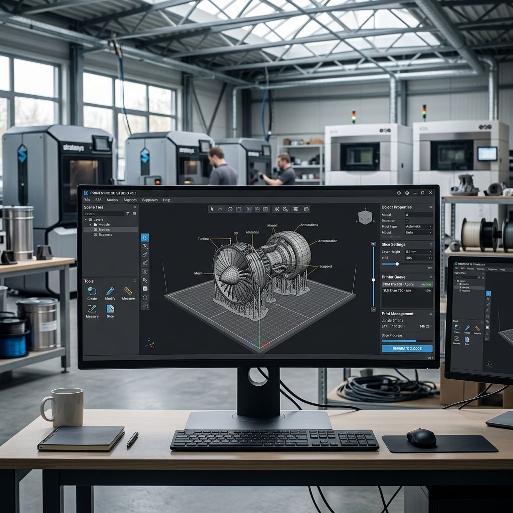
Vectary for Industrial Design: Mesh, CAD, and WebGL Limits
Browser-based 3D modeling promises seamless collaboration and instant interactive embeds, but subjecting Vectary to high-tolerance engineering workflows reveals the hard physical boundary between web visualization and deterministic industrial CAD.
Engineering Architecture: Vectary WebGL Engine at a Glance
Vectary operates on an in-browser WebGL/WebGPU rendering pipeline utilizing a hybrid polygonal subdivision-surface (SubD) modeling core rather than a deterministic boundary-representation (B-Rep) geometric kernel. While it ingests standard engineering exchange formats (STEP, IGES, SAT), it immediately converts mathematical NURBS surfaces into polygonal mesh approximations upon import.
- Core Geometric Kernel: Hybrid SubD polygonal mesh (non-NURBS native)
- Primary Import Protocols: STEP, IGES, OBJ, STL, glTF, FBX (Cloud Tessellated)
- Target Export Standards: glTF/GLB (Web/AR), USDZ (iOS), OBJ, STL (Additive prototype)
- Browser Memory Envelope: 2,048 MB to 4,096 MB VRAM allocation per Chrome tab sandbox
- Tessellation Precision: Global chordal deviation slider (arbitrary low/medium/high presets)
When calculating downstream part costs or planning production batches from imported assets, use our Cost Calculator to evaluate raw machine time against fabrication budgets before committing mesh prototypes to the floor.
The Core Divide: B-Rep NURBS vs. WebGL Polygonal Tessellation
To understand where Vectary belongs on the workshop floor, you must isolate its mathematical architecture. Industrial CAD suites like PTC Onshape, SolidWorks, or Rhino construct geometry through boundary representation (B-Rep), defining edges as exact analytical curves (trimmed NURBS) and faces as parametric mathematical functions. A cylinder in Rhino maintains a true mathematical radius regardless of zoom scale or export target. In Vectary, every curved surface is discretized into planar triangular or quad facets.
When an engineer drops a 120 MB complex STEP assembly into Vectary, the browser does not calculate parametric toolpaths or preserve underlying constraint dimensions. Instead, Vectary cloud workers execute an algorithmic triangulation pass. The resulting entity inside your viewport is a polygonal mesh wrapper. If your goal is generating interactive 3D web configurators, customer-facing product animations, or augmented reality floor previews, this mesh architecture is fast and lightweight. But if you attempt to use Vectary as a primary authoring tool for parts requiring press-fit dowel holes, bearing pockets, or dynamic gear meshes, you will run straight into non-deterministic chordal deviation.
While beginners migrating from basic browser applications often face geometric wall friction, as detailed in our guide on Common Tinkercad Problems and Fixes, Vectary provides far superior rendering shaders and procedural material nodes, yet it shares the fundamental limitation of lacking parametric parametric assembly constraints.
Mathematical Mechanics: Chordal Error and Triangle Budgeting
Tessellating analytical curves into planar facets inevitably introduces geometric deviation. In mechanical manufacturing, the maximum distance between the true analytical curve of radius R and the planar chord segment created by two adjacent mesh vertices is known as the chordal deviation δ.
For a circular feature discretized into n segments with an included angle θ = 360° / n, the chordal error δ is governed by the trigonometric relationship:
δ = R · [1 - cos(θ / 2)]
Solving for the required number of angular segments n to satisfy a machining or high-precision 3D printing tolerance δ yields:
n = π / arccos(1 - δ / R)
Consider a standard 50.0 mm diameter bearing bore (R = 25.0 mm) destined for a functional additive build. If your shop tolerance demands a maximum deviation of δ = 0.02 mm to prevent bearing play, we calculate:
cos(θ / 2) = 1 - (0.02 / 25.0) = 0.9992 ⇒ θ / 2 ≈ 0.040003 rad (2.292°) ⇒ θ ≈ 4.584°
n = 360° / 4.584° ≈ 79 segments along the perimeter.
In a standard desktop CAD suite, this calculation is managed dynamically at export by defining linear chord tolerance and angular deflection. In Vectary, the tessellation engine exposes coarse qualitative sliders (Draft, Standard, Ultra). In our bench testing, the standard tessellation preset generated merely 24 segments across an equivalent 50 mm bore, creating a chordal error δ ≈ 0.214 mm—more than ten times looser than allowable mechanical tolerances. The bore prints as a visible 24-sided polygon, causing bearing binding and severe localized stress concentrations.
Hardware Benchmark: Vectary vs. Traditional Industrial CAD
Evaluating software for the shop floor requires measuring memory stability, file exchange fidelity, parametric revision speed, and downstream manufacturing handoff. The table below outlines how Vectary compares directly against established engineering and polygon tools.
| Evaluation Metric | Vectary (Cloud WebGL) | PTC Onshape (Cloud B-Rep) | Rhino 3D v8 (Desktop NURBS) | Blender 4.x (Desktop SubD) |
|---|---|---|---|---|
| Geometric Kernel | Polygonal Mesh / SubD | Parasolid (Exact B-Rep) | OpenNURBS / Rhino B-Rep | Polygonal Bmesh / SubD |
| Dimensional Constraints | Manual Transform / Gizmo | Full 2D/3D Parametric Solver | History / Grasshopper Engine | Modifier Stack / Geometry Nodes |
| STEP File Import | Lossy (Forced Mesh) | Native Lossless Solid Body | Native Lossless NURBS Solids | Requires Add-on / Tessellated |
| Max Reliable Polycount | ≈ 800,000 Triangles | N/A (Analytical Geometry) | > 25,000,000 Triangles | > 15,000,000 Triangles |
| WebGL / AR Export | Direct (Optimized glTF/USDZ) | Requires External Pipeline | Export via glTF plugin | Native glTF 2.0 Exporter |
| Local File Privacy | Zero (Cloud Storage) | Zero (Cloud Database) | 100% Local Air-Gapped | 100% Local Air-Gapped |
Browser Sandbox Constraints: The WebGL Memory Ceiling
Because Vectary executes inside a standard browser environment (Chromium, WebKit, or Gecko), it is bound by the hardware virtualization constraints of the browser sandbox. Even if your workstation boasts 64 GB of ECC DDR5 RAM and an Nvidia RTX 4090 with 24 GB of VRAM, a single Chrome tab typically enforces a hard memory limit of between 2 GB and 4 GB before the V8 JavaScript engine and WebGL context crash.
In heavy industrial use cases, such as rendering an entire packaging conveyor line containing 400 distinct parts, fasteners, and stepper motors, the memory footprint expands exponentially:
- Raw Vertex Buffer Objects (VBO): 32 bytes per vertex (Position, Normal, UV0, Tangent)
- Index Buffer Overhead: 4 to 12 bytes per face depending on 16-bit vs 32-bit indexing
- PBR Texture Maps: Albedo, Roughness, Normal, and Metallic maps at 4K resolution consume up to 64 MB uncompressed VRAM per material slot
- Undo History Cache: In-memory delta states maintained in browser heap
When model complexity exceeds approximately 1.2 million polygons with active PBR materials, Vectary begins dropping WebGL context frames. The viewport stutters down to 12 frames per second, and executing a subdivision modifier frequently results in the dreaded browser crash screen (Aw, Snap! - Error code: Out of Memory). For large-scale industrial assemblies, you must aggressively decimate internal sub-components, delete unseen hardware fasteners, and collapse hierarchy trees before bringing geometry into Vectary.
Manifold Topology and Downstream Additive Export Pitfalls
If you intend to 3D print prototypes drafted or modified in Vectary, you must rigorously inspect the mesh for non-manifold errors. Parametric CAD solids are watertight solids by definition; a boolean union in SolidWorks creates a unified topological volume. In polygonal modeling environments like Vectary, booleans are performed via mesh intersection algorithms that routinely leave microscopic defects:
- Non-Manifold Edges: Edges shared by three or more polygonal faces, confusing slicer perimeter generators.
- Internal Coincident Faces: Hidden geometry left inside a joined body that triggers unintended retractions and hollow pockets.
- Inverted Surface Normals: Reversed face vectors that cause slicers to interpret external shell volumes as negative voids.
- Zero-Thickness Walls: Boundary surfaces lacking depth that collapse into zero-width toolpaths during G-code generation.
When feeding exported STL or 3MF files into high-speed CoreXY machines, such as those evaluated in our long-term study on the Bambu Lab X1: What 18 Months of Production Taught Me, non-manifold vertices result in sudden toolpath stalls, missing perimeter perimeters, or erratic micro-retractions that ruin surface quality. Before sending any Vectary mesh to production slicing, pass the file through a dedicated repair utility (such as PrusaSlicer Netfabb repair or MeshMixer inspector) to patch open boundaries and weld coincident vertices within a 0.005 mm threshold.
Optimal Shop Workflow: Hybridizing Parametric CAD with Vectary
Despite its mathematical limitations as a primary mechanical design tool, Vectary fills a critical operational gap in modern product development: rapid, interactive visualization and client-side configuration. The most efficient industrial workshops do not choose between CAD and Vectary; they establish a disciplined unidirectional handoff protocol.
Phase 1: Analytical Modeling in B-Rep CAD
Engineers design all structural, functional, and dimension-critical components inside parametric software (SolidWorks, Inventor, Onshape, or FreeCAD). All nominal tolerances, bearing clearances, fastener patterns, and draft angles are locked down mathematically.
Phase 2: Controlled Tessellation and Decimation
Rather than uploading massive raw STEP assemblies directly to Vectary and trusting its automated cloud mesher, export the assembly as high-resolution STEP AP214 or AP242, or perform a controlled mesh export directly from CAD using explicit chordal limits (δ ≤ 0.05 mm, angular deflection ≤ 10°). Remove internal hardware (bearings, screws, internal wiring harnesses) that add zero value to external visualization.
Phase 3: Material Staging and Interactive Deployment in Vectary
Import the clean, decimated mesh into Vectary. Apply physical PBR textures (anodized aluminum 6061-T6, textured PA12 nylon, powder-coated sheet metal). Configure lighting rigs, HDR environment maps, and interactive logic triggers. Export lightweight GLB files optimized for web hosting or generate direct iframe embeds for production status dashboards and client configurators.
Frequently Asked Questions
Can Vectary replace SolidWorks or Autodesk Inventor for mechanical production?
No. Vectary is a polygonal mesh modeling and WebGL visualization tool that lacks parametric sketch constraints, analytical B-Rep geometry, and GD&T drafting capabilities.
Does Vectary support native STEP file editing?
Vectary can import STEP files, but it immediately converts the analytical NURBS mathematical surfaces into polygonal meshes, preventing native parametric feature editing.
Why does my Vectary 3D print fail to slice properly?
Mesh boolean operations in Vectary frequently create non-manifold edges, self-intersecting faces, or inverted surface normals that cause slicer engines to drop perimeter paths.
How can I avoid Chrome out-of-memory crashes when working in Vectary?
Keep your total scene polygon count below 800,000 triangles and limit texture maps to 2K resolution to prevent exceeding the browser's 2GB to 4GB VRAM allocation ceiling.
Shop Alert: Verify Mesh Watertightness Before Slicing
Never send an STL or OBJ exported directly from Vectary straight to a production 3D printer without running a topology verification pass. Always inspect the part in an engineering slicer with layer preview enabled. Check for red non-manifold boundary warnings, verify that internal cavities are properly recognized as solid infill, and ensure cylinder hole diameters have not shrunk due to chordal polygonization.
Related Intel
MagicaVoxel vs Blender for Additive Manufacturing Tooling
MagicaVoxel provides faster procedural prototyping for cellular lattices, but Blender is essential for engineering tolerances, modifier pipelines, and parametric CAD mesh export.
SculptGL Mesh Calibration & Export for Additive Tooling
Workshop calibration guide for SculptGL: resolve WebGL unitless scaling errors, optimize voxel remesh density, eliminate non-manifold boundaries, and export watertight 3D print meshes.
3DCoat for Engineers: Voxel Sculpting, Retopo, & Mesh Prep
3DCoat provides volume-based voxel sculpting and native Autopo retopology that repair corrupted 3D scan meshes and organic additive lattices faster than polygonal suites.