Fixing Optical Decay and Fluid Issues on HeyGears DLP

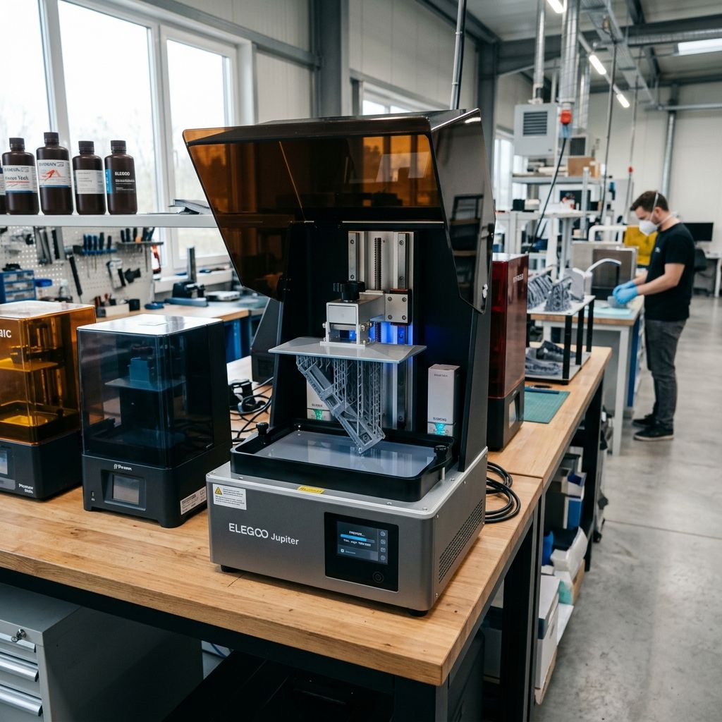
HeyGears Desktop Series: Field Troubleshooting & Industrial Maintenance Log
A veteran technician's breakdown of optical engine decay, peel force dynamics, and fluidic loop failures in high-throughput HeyGears DLP systems.
At a Glance: Industrial Desktop DLP Specifications
HeyGears desktop units (such as the UltraCraft DS and ChairSide series) operate on a highly integrated, closed-loop DLP platform. While marketed as plug-and-play appliances for dental labs and engineering facilities, they are subject to severe mechanical and optical degradation when run on 24/7 production cycles.
If you are encountering print defects or sensor errors, use our 3D Printer Troubleshooting tool to isolate general machine faults before tearing down the optical assembly.
I have spent years maintaining SLA, DLP, and FDM machines in high-volume production facilities. When a HeyGears desktop unit is running well, it is a highly capable machine that outputs incredibly dense, accurate parts. However, its sleek, dental-office exterior hides a complex array of optical, thermal, and fluidic components that do not tolerate shop-floor dust, poor climate control, or neglect.
When these units fail, they do not just stop working; they throw cryptic error codes or, worse, produce parts with subtle dimensional drift that can ruin an entire batch of surgical guides or engineering prototypes. Let's look at the actual failure modes we see on the shop floor, the physics behind why they happen, and how to fix them when you are out of warranty or cannot wait three weeks for a field engineer.
The Realities of the Closed-Loop DLP Architecture
Unlike open-source LCD printers where you can swap out a screen for fifty bucks, the HeyGears platform relies on a tightly controlled optical engine, a pressurized/heated resin delivery system, and proprietary release films. This integration yields high dimensional accuracy, but it also creates failure modes that are difficult to diagnose without specialized knowledge of UV optics and fluid dynamics. If you are used to the simple troubleshooting path of FDM machines such as tracking down extrusion issues as discussed in our industrial FFF analysis you need to shift your mindset. Here, we are dealing with milliwatts of optical power, micro-step runout on heavy Z-axes, and fluid shear stresses.
Failure 1: Optical Engine Decay & Internal Dust Ingress
The core of any DLP system is the optical engine, consisting of a UV LED light source (usually 385nm or 405nm), a Digital Micromirror Device (DMD) chip, and a series of focusing lenses. Marketing materials claim these systems are sealed and maintenance-free. They are not. In real-world lab environments, gypsum dust, resin vapors, and fine particulates bypass the intake filters and settle on the optical pathway.
The Sub-Components and Wear Points
- DMD Chip Cover Glass: The microscopic mirrors on the DMD chip flip thousands of times per second. If organic vapor or fine dust settles on the cover glass, it scatters the UV light, causing localized curing failures.
- UV LED Array Heat Sink: The high-output LEDs generate significant heat. If the heat sink fins clog with dust, the LED junction temperature spikes, causing a rapid drop in optical output.
- Intake and Exhaust Fans: These fans run constantly during operation. If they fail or drop in RPM, the machine will thermal-throttle, reducing UV exposure mid-print and causing layer delamination.
The Physics of Optical Power Degradation
UV LEDs degrade over time, but their decay curve is highly dependent on junction temperature ($T_j$). The optical power output ($P$) of the light engine over time ($t$) can be modeled by the Arrhenius-type degradation equation:
$$P(t) = P_0 \cdot e^{-\alpha \cdot t \cdot e^{-\frac{E_a}{k_B T_j}}}$$
Where:
- $P_0$ is the initial optical power.
- $\alpha$ is a pre-exponential scaling factor.
- $E_a$ is the activation energy of the semiconductor defects.
- $k_B$ is the Boltzmann constant.
- $T_j$ is the junction temperature in Kelvin.
In simple terms: if your cooling path is compromised by dust and the junction temperature rises by just $15^\circ\text{C}$, the rate of UV output degradation triples. This power drop means the resin receives less energy per layer than the slicer expects, leading to soft prints, poor green-state strength, and dimensional runout.
Tech Alert: Never use industrial compressed air to clean the internal optical cavity of a HeyGears printer. The high pressure can force dust past the optical window seals and directly onto the DMD chip face, permanently ruining the optical path. Use only low-pressure, clean, dry instrument air or optical-grade hand bellows.
Field Solution: Deep Optical Cleaning and Power Calibration
- De-energize the Unit: Power down the machine and unplug it from the mains. Allow at least 20 minutes for the UV LED capacitors to discharge and the heat sink to cool.
- Access the Optical Cavity: Remove the rear access panel (this usually requires a hex key set). Locate the optical engine assembly and inspect the intake fan and its associated dust filter.
- Clean the Air Pathway: Vacuum out the heavy accumulation around the heat sink fins. Wash the polyurethane dust filter in warm, soapy water, dry it completely with a lint-free microfiber cloth, and reinstall it.
- Inspect the Protection Glass: Use a high-intensity flashlight to inspect the optical window beneath the resin vat. If you see a hazy film, it is likely vaporized resin monomer that has condensed on the cool glass.
- Clean the Optics: Wet an optical lens wipe (like PEC-PADs) with high-purity (99.9%) Isopropyl Alcohol (IPA). Gently wipe the glass in a single, continuous spiral motion from the center outward. Do not rub back and forth, as this will grind any abrasive particles into the anti-reflective coating.
Failure 2: High Peel Force and Release Film Rupture
DLP printing relies on a cyclic peeling process where each cured layer must detach from the bottom of the resin vat before the Z-axis moves to the next layer height. HeyGears uses proprietary tensioned vats. The peeling motion is a violent mechanical event, especially when printing bulky models or solid engineering blocks.
The Mechanics of VAT Peel Stress
During the peeling phase, the release film deflates and stretches. If the film is under-tensioned, or if the resin viscosity is too high, the peel force exceeds the tensile strength of the thin green-state polymer. This results in the model tearing away from its supports or, in worst-case scenarios, the release film tearing and dumping toxic resin directly onto the optical glass.
The peak peel force ($F_p$) during separation of a flat plate of radius $R$ from a flexible membrane can be estimated using a variation of Stefan's adhesion equation for viscous fluids:
$$F_p = \frac{3 \pi \mu R^4}{2 h^3} \cdot \frac{dh}{dt} + F_{elastic}$$
Where:
- $\mu$ is the dynamic viscosity of the liquid resin.
- $R$ is the equivalent radius of the solid cross-section being printed.
- $h$ is the instantaneous separation distance (layer thickness).
- $\frac{dh}{dt}$ is the Z-axis lift velocity.
- $F_{elastic}$ is the force required to deform the release membrane.
Note how the force scales with $R^4$. If you double the solid cross-sectional area of your model, the peel force increases sixteen-fold if the geometry is circular. This is why hollow structures and smart orientation are mandatory, a concept that mirrors some of the slicing hurdles encountered when optimizing profiles in other slicers, such as those discussed in our troubleshooting guide on Cura slicing errors.
- Expected Film Lifespan: 80 to 120 print hours (dependent on model cross-section and peel speeds).
- Z-Axis Backlash Tolerance: < 5 micrometers (measured with a dial indicator under load).
- Maximum Resin Viscosity Limit: 1200 mPa·s at operating temperature.
- Vat Tension Specification: 250 Hz to 280 Hz (when tested with an acoustic tension meter).
Field Solution: Vat Refurbishment and Peel Parameter Tweak
When you cannot source an immediate OEM replacement vat, you can sometimes rebuild them or adjust slicer parameters to compensate for a fatiguing membrane. Let's walk through the steps to save a job in progress:
- Slicer Support Optimization: If you are getting pull-away failures, open your slicer and increase the contact point diameter of your supports by 15-20%. Add a cross-bracing web to the support structures to resist the lateral shear forces generated during the tilting peel motion.
- Acoustic Tension Tuning: If your machine allows tension adjustments on the vat clamping frame, use a guitar tuner app on your phone. Tap the center of the clean, dry film. A properly tensioned HeyGears-style vat should resonate between 250 Hz and 280 Hz. Tighten the perimeter screws in a star pattern (like a car wheel) to raise the pitch uniformly.
- Implement Lift Delays: If your resin is highly viscous (such as temporary crown/bridge resins or high-temp engineering resins), increase the "Rest Time Before Exposure" and "Rest Time After Lift" in the parameter editor. This allows the fluid to flow back under the build plate and stabilizes the pressure differential before the UV light hits the resin.
Failure 3: Thermal Loop & Fluid Level Sensor Malfunctions
HeyGears printers feature an active heating chamber and an automated resin dispensing loop. To maintain consistent resin viscosity, the interior chamber is kept warm, and sensors monitor the liquid level in the vat to pump in fresh resin from the cartridge. This automation is convenient until a sensor gets coated in cured resin or the heating loop fails.
Viscosity vs. Temperature Curve of Dental Resins
Resin viscosity ($\mu$) is highly temperature-dependent and follows an Arrhenius relationship:
$$\mu(T) = \mu_0 \cdot e^{\frac{E_{\nu}}{R_g T}}$$
Where $E_{\nu}$ is the activation energy for viscous flow, $R_g$ is the gas constant, and $T$ is the absolute temperature in Kelvin.
If the printer's heating chamber drops from its set point of $35^\circ\text{C}$ to a room temperature of $20^\circ\text{C}$, the viscosity of typical dental resins can double or even triple. This causes massive shear stresses during the "squeeze" phase of the print cycle, causing thin supports to buckle and fine details to wash out.
The Level Sensor Failure Loop
The level sensor is usually an optical or capacitive probe situated near the top edge of the vat. Over time, splashing resin, surface foam, or polymerization from scattered UV light creates a cured skin over the sensor face. The machine then misreads the level, leading to two equally frustrating scenarios:
- The printer thinks the vat is empty, halts the job mid-print, and locks you out until you clear the "Resin Level Low" error.
- The printer thinks the vat is empty when it is actually full, continues to pump resin from the cartridge, and overflows the vat, sending raw resin down into the internal mechanical linkages and optical assembly.
Preventive Action: Level Sensor Calibrations
To avoid catastrophic vat overflows or dry runs, perform a sensor verification every 50 hours of print time. Clean the sensor face with pure IPA and run the built-in diagnostic test from the maintenance menu. If you are experiencing constant mechanical failures, our 3D Printer Troubleshooting system can guide you through isolating structural sensor faults from software lockouts.
Field Solution: De-crusting the Sensor and Heater Diagnostic
- Locate the Probe: Open the chamber door and locate the sensor array mounted on the carriage arm above the vat.
- Chemical De-crusting: Soak a cotton swab in warm IPA (heated to about $40^\circ\text{C}$ by placing the container in a warm water bath never heat IPA with an open flame or direct heating element). Gently press the warm swab against the sensor face to soften any cured monomer.
- Mechanical Scraping (Ultra-Low Force): Use a plastic clay modeling tool or a wooden toothpick to scrape away the softened crust. Do not use metal dental picks or brass wire brushes; if you scratch the face of an optical sensor, you will permanently degrade its refractive properties, requiring a full sensor replacement.
- Verify the Heater Loop: If the chamber is failing to reach temperature, check the PTC heater element located behind the air circulation vent. Use a multimeter to check the resistance across the heater terminals. A healthy heating element should read between 15 and 45 Ohms. A reading of infinity indicates an open circuit, meaning the heating element has burned out and must be replaced.
Comprehensive Slicer & Parameter Settings for Industrial Resins
To prevent mechanical failures, you must tailor your slicer profiles to match the physical properties of the material you are running. Below is a reference chart of optimized print parameters for common resin classes on HeyGears-compatible engines.
- Dental Model Resin: Exposure: 2.1s | Lift Speed: 120 mm/min | Rest Before: 1.5s | Chamber Temp: 35°C
- Biocompatible Surgical Guide: Exposure: 2.8s | Lift Speed: 80 mm/min | Rest Before: 2.5s | Chamber Temp: 38°C
- High-Temperature Engineering Polymer: Exposure: 3.2s | Lift Speed: 60 mm/min | Rest Before: 4.0s | Chamber Temp: 40°C
- Flexible Gasket Resin: Exposure: 3.5s | Lift Speed: 50 mm/min | Rest Before: 5.0s | Chamber Temp: 35°C
Troubleshooting Matrix: Symptom, Root Cause, and Field Remedy
This table acts as a quick-reference guide for technicians diagnosing issues on the shop floor under tight deadlines.
| Observed Symptom on Build Plate | Probable Root Cause | Immediate Field Remedy |
|---|---|---|
| Localized "holes" or missing features always in the same area of the build platform. | Dust or cured resin debris on the optical window or DMD mirror. | Clean the protective optical window with optical wipes and 99.9% IPA. Check the underside of the vat for cured resin flakes. |
| Models splitting horizontally across layers (delamination). | Sudden temperature drop in the chamber or excessive lift speed on a thick section. | Verify PTC heater operation. Reduce Z-axis lift speed to 60 mm/min and increase rest time after print. |
| The printer throws a "Cartridge Empty" error when the cartridge is clearly full. | RFID chip reader failure or resin level sensor miscalibration. | Clean the cartridge seat contacts. Wipe down the level sensor probe and run a manual sensor calibration cycle. |
| Models are dimensionally oversized along the X and Y axes, making assembly fits impossible. | UV light bleed or excessive exposure settings in the material profile. | Reduce base exposure time by 0.2-0.4 seconds. Check for internal optical scattering from a hazy cover glass. |
Frequently Asked Questions
Why does my HeyGears printer keep halting mid-print with a Z-axis overload error?
This is almost always caused by excessive peel forces. If your model has a large solid cross-section, the suction force on the bottom of the vat can exceed the torque limit of the Z-axis stepper motor. To fix this, hollow your parts, add drain holes as close to the build plate as possible, and reduce your lift speed in the slicer to 60 mm/min or less.
Can I use third-party resins in my HeyGears Desktop printer?
HeyGears printers are designed as a closed ecosystem with proprietary cartridges. While some models allow open-material mode via an advanced license, running unvalidated third-party resins often leads to failed prints because the optical wavelengths and energy delivery curves are highly tuned to HeyGears' own chemical formulations. If you do run third-party resins, you must manually calibrate exposure times using a calibration matrix print.
How often should I calibrate the optical power of the DLP projector?
Under heavy production use (more than 40 hours of print time per week), you should measure and calibrate the optical output every six months. Use an external radiometer tuned to the specific wavelength of your light source (usually 385nm) to ensure the engine is delivering the correct milliwatts per square centimeter ($mW/cm^2$) across the entire build area.
What causes a cloudy finish on parts that should be optically clear?
Cloudiness is usually caused by insufficient post-processing or resin contamination. Ensure the parts are washed in clean, two-stage IPA baths (the first bath for bulk removal, the second with clean solvent to prevent residue). Allow the parts to dry completely before post-curing, as curing wet parts traps micro-droplets of solvent on the surface, creating a frosted, hazy appearance.
Critical Torque & Material Handling Specification
When reinstalling the resin vat after cleaning, tighten the clamping screws to 1.2 Nm. Over-tightening can warp the vat chassis, causing optical distortion along the edges of the build plate and inducing micro-fractures in the aluminum frame. Always wear nitrile gloves when handling the vat and optical components; skin oils absorb UV light and can create hot spots on the optical window, leading to premature glass cracking under thermal load.
Related Intel
Anycubic Photon Mono M7 Max and M5s Pro Review
An in-depth engineering review of Anycubic Photon Mono M7 Max and M5s Pro resin 3D printers, analyzing 14K optics, ACF peel physics, and Z-axis cantilever rigidity.
UniFormation GKTwo 12K Review and Comparison
The UniFormation GKTwo 12K combines a 29.7 µm 10.3-inch LCD with an integrated PTC vat heater and quick-release hardware, solving cold-resin failures in production workshops.
Common Elegoo Mars 5 and Mars 5 Ultra Issues
Learn how to fix common Elegoo Mars 5 and Mars 5 Ultra issues: tilt mechanism binding from resin contamination, force sensor leveling failures, and release film fatigue. Includes step-by-step rebuild workflows.