Anycubic Photon M7 Max and M5s Pro Common Issues

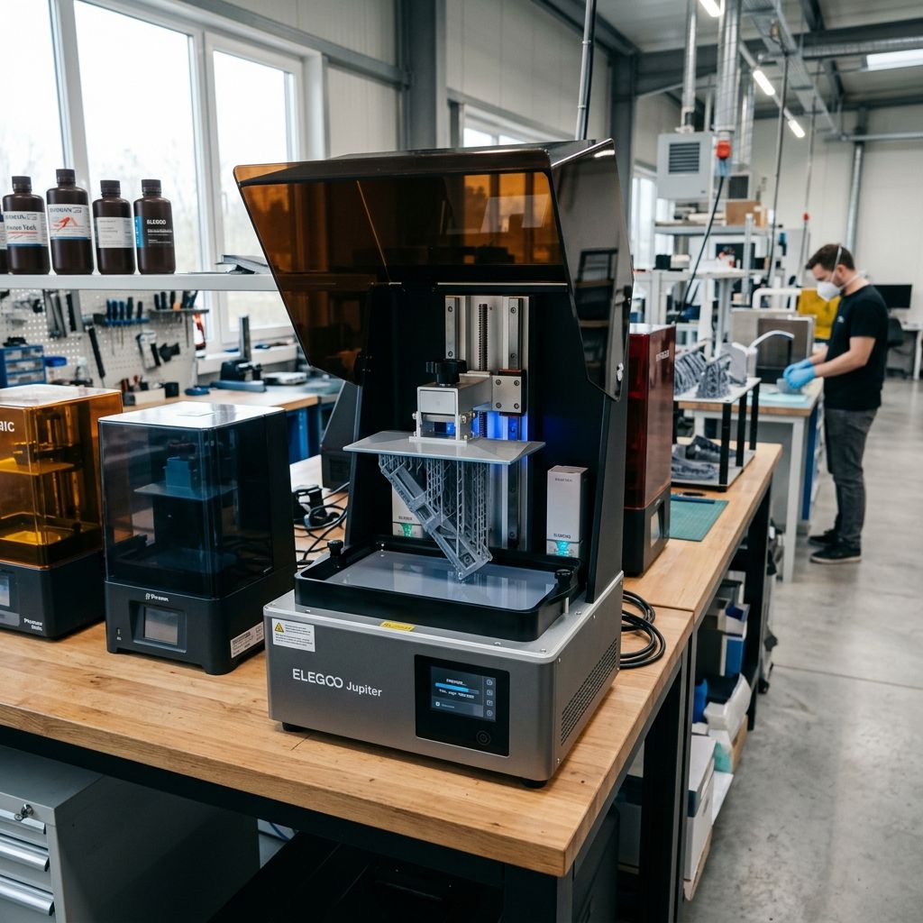
Anycubic Photon Mono M7 Max & M5s Pro: Field Troubleshooting & Community Solutions
An unfiltered engineering teardown of the auto-leveling failure points, peel-force physics, thermal control issues, and real-world shop fixes for Anycubic's large-format resin flagships.
Field Highlights & Operating Metrics
The Anycubic Photon Mono M7 Max and M5s Pro represent a massive push toward high-throughput, "hands-off" resin printing. However, eliminating manual leveling and ramping up lift speeds introduces severe physical strains on the cantilever assembly, peel membrane, and force-sensing arrays.
If you are experiencing persistent printing issues or mechanical errors, use our 3D Printer Troubleshooting Tool to pinpoint root causes and calculate optimal recovery steps.
Large-format resin printing is a brutal exercise in mechanics. When you scale up to a 10.1-inch or 13.6-inch LCD panel, the physics of polymer release forces do not scale linearly they scale exponentially. While marketing materials promise seamless "leveling-free" operations and blistering speeds up to 150mm/hr, any tech who has run these machines in a job shop for 500+ hours knows that the reality on the ground is far messier.
Both the Anycubic Photon Mono M5s Pro and the newer Photon Mono M7 Max share a common architecture designed to minimize user intervention: strain-gauge sensor arrays embedded behind the cantilever connection, active resin vat heating loops, and high-flex ACF (Fluorine-doped Ethylene Propylene) or high-tensile release films. When these systems are in harmony, they yield incredible throughput. When they drift, they turn into expensive resin-curing pools that waste liters of material and ruin schedules.
Here is the teardown of why these machines fail under heavy duty, how to diagnose them, and how to fix them when factory support tells you to just "re-slice the file."
---1. The Mechanical Reality of "Level-Free" Systems: Strain Gauge Failures
The M5s Pro and M7 Max do not use manual 4-point bed leveling screws. Instead, they rely on a floating cantilever mount backed by an array of strain gauges (piezoelectric pressure sensors) located inside the Z-axis carriage. During the homing sequence, the build plate moves down until it contacts the LCD screen. The physical resistance of this contact transmits a force back up through the cantilever arm, which register on the load cells. Once a specific force threshold (typically 1.5 to 2.5 kg of force) is reached across the sensors, the firmware defines this coordinate as the absolute Z-zero position.
This sounds elegant, but in a dusty, chemical-heavy workshop, several failure modes plague this mechanism:
Resin Contamination and Mechanical Hysteresis
If a tiny drop of cured resin drips onto the sliding guide pins of the floating build plate bracket, or if the internal springs lose their tension over hundreds of cycles, the plate will no longer float freely. This creates mechanical binding. When the Z-axis homes, the binding prevents the plate from conforming to the LCD glass. The sensors detect force prematurely, setting Z-zero too high. The result? The first layer prints in mid-air, leaving a cured pancake of resin stuck to the bottom of your vat.
Thermal Drift of the Strain Gauges
Strain gauges work by measuring tiny changes in electrical resistance caused by the physical deformation of a foil pattern. These sensors are incredibly sensitive to temperature fluctuations. When the internal vat heater runs, it warms not just the resin, but also the metal chassis of the printer and the Z-carriage. As the metal expands, it introduces structural stress on the strain gauges. This thermal drift causes the controller board to read false values, making the auto-leveling routine either fail outright (throwing a "Leveling Sensor Error" or "Z-Axis Limit Overrun") or home with excessive force, crushing the protective glass over the LCD.
This sensor drift is highly reminiscent of the calibration drift seen on advanced extrusion platforms, such as the load-cell sensor issues described in our teardown of the Bambu Lab X1C/X1E Common Errors and Fixes. In both cases, relying on automated physical-contact sensors means you are at the mercy of mechanical cleanlines and thermal stability.
- Optimal Sensor Temperature: 22°C 28°C (Stable thermal equilibrium is required before homing)
- Trigger Force Threshold: 18N to 25N of resistance load
- Z-Axis Carriage Backlash Tolerance: < 0.01mm
- Average Strain Gauge Lifespan: 1200 - 1800 duty cycles before sensor creep occurs
2. The Physics of Peel Forces and High-Speed ACF Failures
Anycubic utilizes ACF (release film with a rough, low-surface-energy surface) to enable high print speeds. Standard FEP or NFEP films rely on a high-peel deflection profile the film has to stretch and bow significantly before the cured resin layer releases. ACF has a higher tensile modulus (it is stiffer) and a micro-textured contact face that reduces suction forces by preventing a perfect vacuum seal between the cured layer and the film.
However, this stiffness is a double-edged sword. If your lift speeds are set too high, or if you are printing parts with large, solid cross-sections, the physical forces exerted on the Z-axis, the LCD glass, and the build plate are astronomical.
The Math of Suction: Why Large Parts Ruin the Vat
To understand why prints fail or tear the release film on these machines, we look to Stefan's Adhesion / Squeeze Flow Equation. For two parallel flat plates of radius $R$ separated by a fluid of dynamic viscosity $\eta$ and gap height $h$, the force required to pull them apart at a velocity of $v = \frac{dh}{dt}$ is expressed as:
Stefan Adhesion Equation:
$$F_{peel} = \frac{3 \pi \eta R^4}{2 h^3} \frac{dh}{dt}$$
Where:
- $F_{peel}$ = The total upward force exerted on the build plate (Newtons)
- $\eta$ = The dynamic viscosity of the resin (Pascal-seconds, Pa·s)
- $R$ = The equivalent radius of the printed part's solid cross-section (meters)
- $h$ = The liquid resin gap height (meters) during initial layer separation
- $dh/dt$ = The Z-axis lift velocity (meters/second)
Look closely at the exponents. The peel force scales with the fourth power of the radius ($R^4$) and is inversely proportional to the cube of the gap height ($h^3$).
If you double the radius of a solid block on your M7 Max (e.g., printing a solid enclosure instead of a hollowed one), you are increasing the instantaneous peel force by a factor of sixteen ($2^4 = 16$)! If you combine this large cross-section with cold, highly viscous resin (high $\eta$) and a fast lift speed ($dh/dt$), the peel force easily exceeds the tensile strength of the ACF film or the maximum holding torque of the Z-axis stepper motor. The film stretches past its elastic limit, creating a permanent cloudy dent (plastic deformation), or it tears entirely, dumping 2 liters of toxic resin into the chassis.
This mechanical stress can also be compounded by slicer anomalies. For instance, incorrect peel-delay parameters or lift acceleration profiles in your software will translate to brutal physical forces on the hardware. Understanding these software-to-hardware relationships is similar to diagnosing issues with slicing engines, such as the bugs covered in Cura Slicing Errors and Missing Layers, where incorrect acceleration or retraction parameters cause physical prints to tear or fail mid-process.
---3. Resin Heating System Anomalies & Thermal Gradients
Both the M5s Pro and the M7 Max feature active resin heating modules. The M5s Pro uses an external, clip-on forced air heater/purifier combo, while the M7 Max features an integrated vat heater that warms the resin basin directly. Keeping the resin at a steady $25^\circ\text{C}$ to $35^\circ\text{C}$ is vital for lowering dynamic viscosity ($\eta$), which, as shown in Stefan's equation, directly reduces the peel forces. Warm resin also polymerizes much faster and more consistently.
In the field, however, these heating loops are notorious failure points:
Localized Thermal Hotspots
The heating element does not heat the vat uniformly. The area closest to the heating element (usually the rear of the vat) can reach up to $45^\circ\text{C}$, while the front corners remain at ambient shop temperature (often $15^\circ\text{C}$ $18^\circ\text{C}$ in winter). This thermal gradient causes uneven polymerization. Prints located at the back of the build plate will cure faster and over-expose, while prints at the front will under-expose, delaminate, and fall into the vat.
Thermistor Failure & "Dry Run" Errors
The heater's controller board relies on a tiny thermistor touching the underside of the vat or embedded in the heating block. If you remove the vat for cleaning and do not seat it perfectly flat against the heater contacts when reinstalling, the thermistor will read air temperature instead of resin temperature. The control loop will continuously pump current to the heating element, overheating the heater until the thermal fuse blows or the printer throws a safety shutdown code (e.g., "T-Sensor Error").
---4. Step-by-Step Field Maintenance & Restoration Workflows
If your machine is throwing leveling errors, producing warped prints, or making loud popping noises during the peel cycle, you need to execute a systematic restoration. Do not rely on the factory's automated routines until you have verified the physical geometry of the machine.
Workflow A: Cleaning and Overhauling the Strain Gauge / Cantilever Assembly
This procedure resolves false Z-zero calibration readings and "Leveling Sensor Errors."
- Isolate and Power Down: Turn off the printer and unplug the power cable. Remove the build plate and the resin vat. Wipe down all surfaces with 99% Isopropyl Alcohol (IPA) to ensure no wet resin can migrate into the screw holes.
- Expose the Floating Bracket: On the back of the Z-axis carriage, locate the shroud covering the cantilever mechanism. Remove the four M3 hex screws securing this plastic cover.
- Inspect the Springs and Pins: Locate the spring-loaded pins that allow the build plate mounting arm to compress slightly when contacting the screen. Spray these pins with electronic cleaner (contact cleaner) to dissolve any ingress of resin. Work the bracket up and down manually. It must move smoothly with zero catching or gritty resistance.
- Check Strain Gauge Wiring: Inspect the delicate ribbon cables or thin wire pairs running from the strain gauges to the internal daughterboard on the carriage. Look for pinches, insulation wear, or loose connectors. Secure loose connectors with a dot of electronics-grade silicone adhesive (non-corrosive).
- Reassemble and Pre-Tension: Reinstall the shroud. Ensure the mounting bolts are tightened to exactly 1.2 Nm of torque using a calibrated micro-torque wrench. Over-tightening these bolts pre-loads the strain gauges, making them overly sensitive or completely unresponsive.
Workflow B: ACF/FEP Film Replacement and Tension Calibration
Do not just screw the new film into the vat randomly. Resin vats are mechanical drums that require specific tensioning to peel correctly.
- Strip the Vat: Remove all M2 hex screws from the tensioning ring on the bottom of the vat (there are typically 24 to 32 screws depending on the model). Discard the old film. Clean the vat frame and the tension ring thoroughly with IPA, removing all cured resin debris from the screw recesses.
- Prep the Spacer: Place a clean, soft foam block or a 3D-printed tensioning jig (approx. 5mm to 8mm thick) in the center of the upside-down vat. This jig acts as a displacement spacer to ensure the film has the correct amount of slack before it is clamped down.
- Lay the Film: Place the new ACF film over the vat bottom. Note the orientation: ACF has a glossy side and a matte (textured) side. The matte side must face the resin (upward into the vat); the glossy side must face the LCD glass. Putting it in upside down will cause severe sticking and instantly ruin the film on the first print.
- Diagonal Clamping: Place the tensioning ring over the film. Using a hand driver (do not use an electric screwdriver you will strip the aluminum threads in the vat), install the screws in an "X" or star pattern. Tighten them initially to finger tightness.
- Final Tensioning: Drive the screws down fully. As you tighten, the film will draw down around the edges of the vat, stretching over the spacer block. This creates the correct elastic tension.
- The Audio Spectrum Test (The Pro Tip): Download a guitar tuner app or an audio spectrum analyzer on your phone. Tap the center of the installed film with a soft plastic tool. The resonant frequency of a properly tensioned large-format ACF film should sit between 140 Hz and 165 Hz. If it is lower than 130 Hz, it is too loose and will fail to peel. If it is higher than 180 Hz, it is too tight and is highly prone to tearing under high suction forces.
5. Mechanical Troubleshooting Matrix
Keep this matrix printed near your workbench. It cuts through the fluff and targets the physical root cause of common issues.
| Symptom | Probable Root Cause | Field Diagnostic Action | Permanent Workshop Fix |
|---|---|---|---|
| Print fails to stick to build plate; cured resin disk found on ACF bottom. | Auto-leveling failure; Z-zero set too high due to strain gauge pre-loading or mechanical binding. | Check Z-axis carriage for resin drips. Manually compress the floating plate to see if it springs back freely. | Disassemble cantilever bracket, clean guide pins with contact cleaner, and torque shroud bolts to 1.2 Nm. |
| Loud "popping" sound on early layers followed by a "Z-Axis Motor Stall" error. | Excessive peel force (suction) exceeding stepper motor torque or stretching ACF. | Check dynamic viscosity of resin (is it cold?). Measure cross-sectional surface area of the model in the slicer. | Warm resin to 30°C. Reduce lift speed by 40% for the first 10 layers, or hollow the model and add vent holes close to the build plate. |
| Repetitive lines/horizontal bands across the print at identical Z-heights. | Z-axis lead screw runout (bent screw) or linear rail carriage slop. | Run the Z-axis up and down manually. Watch the lead screw from the side to detect physical runout (wobble). | Clean lead screw with a brass wire brush, remove factory grease, and apply high-grade PTFE grease. If bent, replace the lead screw. |
| "T-Sensor Error" / Active heating system fails to activate. | Poor vat contact with thermal interface pins or blown thermal fuse in heater. | Check the spring-loaded pogo pins on the printer chassis behind the vat. Are they stuck down or coated in resin? | Clean pogo contacts with IPA and a cotton swab. Ensure the vat thumbscrews are tightened evenly to clamp the vat against the sensor. |
| ACF film clouds or deforms permanently after only 3 or 4 prints. | Local over-exposure or excessive local peel force stretching the film past its elastic limit. | Check exposure settings. Standard exposure for ACF should be 10-15% lower than FEP due to different light transmission rates. | Calibrate exposure times using a calibration matrix. Ensure you are using a transition layer count of at least 6 layers to step down exposure smoothly. |
6. Technical Alternatives & Hacky Field Fixes
When you are in the middle of a production run and don't have time to wait three weeks for Anycubic to ship replacement parts from overseas, these workshop-proven workarounds can keep your line running.
The Manual Leveling Mod: Eliminating the Ghost in the Machine
If your strain-gauge leveling sensor array is completely shot and constantly throwing errors, you can convert the M5s Pro or M7 Max into a rigid, manual-leveling machine. This bypasses the sensor circuit entirely, allowing you to print while you wait for a replacement carriage assembly.
CRITICAL WARNING: This mod bypasses built-in hardware safety checks. You must execute manual homing with extreme caution to avoid cracking your LCD screen. Always place a sheet of paper over the LCD during initial calibration and lower the Z-axis in 0.1mm increments.
- Lock Out the Float: Remove the cantilever carriage shroud. Locate the internal compression springs that allow the build plate mount to float.
- Insert Rigid Spacers: Insert precision steel washers (M3 or M4, depending on the model's guide pin size) over the guide pins to take up all the spring slack. When you reinstall the plate and tighten the bolts, the mount will now be locked into a completely rigid state with zero mechanical play.
- The Manual Homing Hack: Loosen the four main mounting screws on the sides of your build plate bracket. Place a leveling paper over the LCD. Manually run the Z-axis down via the touchscreen in 1mm and then 0.1mm steps until the plate sits flat and flush on the paper, compressing it evenly.
- Torque It Down: Tighten the plate bracket screws while pressing down evenly on the center of the build plate.
- Tricking the Firmware: Because the strain gauges won't detect the home signal since we locked them out, you must set the new Z-zero position manually in the settings menu ("Set Z=0"). If the firmware refuses to bypass the auto-leveling routine, you can plug a custom G-code script into your sliced files to override the start sequence, forcing the machine to read your manual coordinate instead of calling the `G28` auto-homing macro.
Rain-X / PTFE Coating on ACF: The Release Force Lifesaver
If you are printing incredibly complex, fragile geometries or highly viscous engineering resins (like high-temp or flexible resins) and are constantly fighting delamination, you can chemically modify the release characteristics of your film. Apply a thin layer of hydrophobic glass treatment (like standard automotive Rain-X) or a dry PTFE lubricant spray to the vat side of the ACF film. Let it dry completely for 10 minutes, then buff it out with a clean microfiber cloth until the film is perfectly transparent. This leaves an ultra-thin, low-surface-energy layer that reduces the physical adhesion coefficient of the cured resin by up to 30%, drastically lowering the $F_{peel}$ force during operation.
---Frequently Asked Questions
Why does my M7 Max make a loud screeching noise when lifting the Z-axis on heavy prints?
This is usually due to stick-slip friction on the dual linear guide rails or dry lead screw threads. Under high cantilever peel loads, the carriages are twisted slightly, causing binding against the rails. Clean the rails with mineral spirits and apply a high-viscosity synthetic grease with PTFE (like Super Lube 21030) directly to the bearing raceways.
Can I swap the ACF film on my M5s Pro for standard FEP to save money?
You can, but you must completely rewrite your slicer settings. Standard FEP has a much lower tensile modulus than ACF, requiring a larger lift height (typically 8-10mm instead of 5-6mm) and significantly lower lift speeds (maximum 60-80mm/min instead of 150+mm/min) to allow the film to release without tearing your prints.
The build plate heater on my M5s Pro keeps turning off mid-print. What is wrong?
The external heater/purifier combo monitors the ambient air temperature within the chamber. If the chamber reaches its target temperature (typically set via the heater's onboard screen), the heater cycles off. However, if the unit loses connection with the mainboard due to poor contact pin mating, or if the mainboard detects a safety timeout, it cuts power to the accessory port. Clean the connection contacts on the rear column with isopropyl alcohol.
My prints look mathematically correct on the back of the plate but are squished on the front. How do I fix this?
This is a classic symptom of cantilever arm deflection. Under high suction forces, the heavy build plate assembly flexes the Z-axis carriage forward. Ensure your vat is not over-tightened on one side, clean the front-facing linear rail carriages, and orient your model in the slicer so that the larger solid cross-sections are positioned closer to the Z-axis column to minimize torque leverage.
FINAL WORKSHOP WARNING: Resin printers are chemical reactors operating under mechanical loads. Always inspect your vat film after any print failure before starting another job. A tiny cured shard of resin left on the bottom of the vat will act as a solid anvil when the machine auto-homes for the next print, concentrating all homing force into a single point and instantly shattering your $400 LCD screen. Keep your vat clean, keep your resin warm, and never trust a machine to level itself without checking its math.
Related Intel
Anycubic Photon Mono M7 Max and M5s Pro Review
An in-depth engineering review of Anycubic Photon Mono M7 Max and M5s Pro resin 3D printers, analyzing 14K optics, ACF peel physics, and Z-axis cantilever rigidity.
UniFormation GKTwo 12K Review and Comparison
The UniFormation GKTwo 12K combines a 29.7 µm 10.3-inch LCD with an integrated PTC vat heater and quick-release hardware, solving cold-resin failures in production workshops.
Common Elegoo Mars 5 and Mars 5 Ultra Issues
Learn how to fix common Elegoo Mars 5 and Mars 5 Ultra issues: tilt mechanism binding from resin contamination, force sensor leveling failures, and release film fatigue. Includes step-by-step rebuild workflows.