Elegoo Saturn 3 Ultra Hardware Failures and Repairs

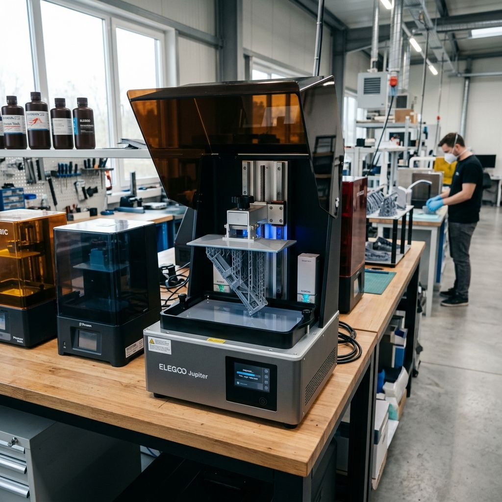
Elegoo Saturn 3 Ultra Hardware Failures: Shop Diagnosis and Component Rebuilds
High-speed MSLA printing pushes ACF release films, linear ball screws, and 12K LCD thermal thresholds to mechanical limits under sustained workshop workloads.
Engineering Cause-Effect Summary: Dynamic Stress in High-Speed MSLA
The Saturn 3 Ultra increases volumetric throughput by pairing a 12K mono LCD with composite ACF (Fluoropolymer Composite Release) film and high-acceleration Z-axis travel. However, accelerating lift speeds to 300 mm/min dramatically multiplies hydraulic peel tension at the vat interface. When resin viscosity fluctuates or vat tension drops below resonant frequency specifications, mechanical failures cascade into torn films, Z-axis lead screw binding, and pixel degradation. Use our 3D Printer Troubleshooting tool to isolate software slice variables before tearing down sub-assemblies.
ACF Film Mechanics: Release Force, Elastic Modulus, and Rupture Points
The introduction of ACF film is the architectural core of the Saturn 3 Ultra's high-speed capability. Unlike traditional FEP or PFA (nFEP) membranes, ACF features a textured micro-rough surface on the resin contact side that breaks vacuum suction through controlled air entrapment. While this reduces separation forces during initial lift phases, ACF has a significantly lower ultimate tensile elongation before permanent deformation.
Under repeated peel cycles with dense solid cross-sections, ACF exhibits localized plastic elongation, often termed "cupping." Once the film yields past its elastic limit, the center of the vat sags, failing to clear the cured layer during standard 3 mm to 4 mm lift heights. Cured resin subsequently crushes against the LCD glass during the subsequent downward descent, cracking the 12K display panel.
Microscopic analysis of spent ACF sheets reveals pinhole ruptures originating at stress concentration nodes where cured pigment precipitates settle. When abrasive filler particulates, such as ceramic-doped or carbon-fiber micro-slurries, become trapped between the descending build plate and the tensioned sheet, localized compressive loads exceed the composite film's shear limit of 42 MPa, puncturing the barrier.
The Physics of Stefan Adhesion and Hydraulic Suction
The mechanical force required to detach a freshly photopolymerized resin layer from the vat floor is governed by Stefan's adhesion equation for parallel disks separated by a viscous liquid film. The separation force \( F_{\text{peel}} \) is formulated as:
$$F_{\text{peel}} = \frac{3 \pi \eta r^4}{2 h^3} \cdot \frac{dh}{dt}$$
Where:
- \( \eta \) represents the dynamic viscosity of the resin (measured in Pa·s).
- \( r \) is the equivalent hydrodynamic radius of the cross-sectional layer boundary.
- \( h \) is the instantaneous separation clearance between cured photopolymer and the release film.
- \( \frac{dh}{dt} \) is the initial vertical lift velocity commanded by the stepper motor.
Because release tension scales with the fourth power of cross-sectional radius (\( r^4 \)) and inversely with the cube of initial separation distance (\( h^3 \)), large architectural bases or solid tooling fixtures generate extreme localized peel tension exceeding 180 Newtons. At lift speeds of 300 mm/min (\( 5 \text{ mm/s} \)), cold engineering resins (\( >800 \text{ mPa}\cdot\text{s} \)) create instantaneous vacuum loads that shear support tips clean off parts.
ACF Tension Tuning and Vat Torque Specifications
Replacing an ACF sheet on the Saturn 3 Ultra requires disciplined acoustic or deflection tuning. Technicians accustomed to tuning FEP to 300-350 Hz via frequency spectrum apps must adjust their targets for ACF. Due to the composite backing layer, ACF requires a lower resting frequency to avoid premature corner tearing along the gasket perimeter.
| Film Material | Thickness (µm) | Acoustic Frequency Range (Hz) | Elastic Modulus (MPa) | Max Recommended Lift Speed |
|---|---|---|---|---|
| ACF Composite | 300 | 240 - 280 Hz | 850 | 300 mm/min |
| PFA (nFEP) | 150 | 310 - 340 Hz | 550 | 120 mm/min |
| Standard FEP | 127 | 320 - 360 Hz | 480 | 80 mm/min |
| PTFE Hybrid | 200 | 260 - 290 Hz | 720 | 180 mm/min |
When torquing the twenty-eight perimeter tensioning screws, use a crisscross star pattern in two passes: first to 0.4 Nm, then finishing at exactly 0.8 Nm. Over-tightening corners induces biaxial shear stresses that cause edge splits after fewer than 2,000 layers.
Always inspect the aluminum clamping ring for burs before seating replacement sheets. Even a microscopic metal chip pinched against the silicone gasket creates a localized pressure point that guarantees an unrecoverable leak into the optical chamber during overnight production runs.
Z-Axis Ball Screw Diagnostic and Backlash Management
The Saturn 3 Ultra upgrades from conventional brass leadscrew nuts to an integrated recirculating ball screw assembly. This eliminates axial backlash and improves layer registration along the vertical travel axis. However, ball screws are far more sensitive to particulate contamination and improper lubrication than traditional trapezoidal screws.
Cured resin mist, airborne photopolymer aerosols, and workshop dust adhere to the ground thread tracks. When ball bearings encounter hardened debris, they skid rather than roll, causing micro-pitting on the hardened steel screw shaft. The symptom presents as periodic horizontal banding spaced exactly at the pitch distance of the screw (4 mm pitch on the Ultra). Inspecting hardware wear requires the same attention to moving components documented in our Elegoo Centauri Carbon Wear Parts Replacement Guide.
- Step 1 (Inspection): Clean the ball screw threads using isopropyl alcohol and a lint-free nylon brush to remove oil sludge.
- Step 2 (Deflection Check): Mount a dial indicator to the cantilever arm with the stylus resting on the aluminum gantry frame.
- Step 3 (Backlash Test): Command a 0.05 mm jog up followed by 0.05 mm down; needle movement must register within 0.008 mm.
- Step 4 (Coupler Torque): Check the lower flexible helical coupler clamp bolt; torque must read 2.2 Nm on the 5mm shaft interface.
- Step 5 (Lubrication): Apply high-viscosity perfluoropolyether (PFPE) or synthetic lithium grease (NLGI Grade 2) along the ball tracks.
- Step 6 (Carriage Tramming): Verify parallel alignment between the dual linear rails and the central ball screw using precision calipers.
12K Mono LCD Thermal Degradation and Light Engine Failure
The 10-inch 12K monochrome LCD achieves 11520 x 5120 resolution with an XY pixel size of 19 x 24 microns. However, transmitting 405 nm UV light through polarizing filters generates substantial thermal energy. The internal COB (Chip-on-Board) refractive light source generates up to 110 watts of heat during continuous exposures.
If chassis exhaust fans become clogged or room ambient temperature climbs above 32°C, thermal soaking causes the liquid crystal alignment layer to break down. This presents as permanent dark clouds, ghost pixels, or UV light bleed through unpowered sub-pixels. Once liquid crystal organic compounds degrade from excessive thermal exposure, the screen cannot be repaired and must be replaced.
Similar to thermal management problems observed when Fixing Common UltiMaker Method XL Problems, unmonitored thermal cycles warp nearby structural chassis components and degrade internal electronics.
Technicians should measure UV irradiance periodically using a calibrated 405 nm radiometer placed flat upon the LCD surface. A factory-fresh screen outputs between 4.8 and 5.5 mW/cm². When peak irradiance drops below 3.6 mW/cm² across central exposure zones, exposure times must be lengthened, indicating the onset of LED chip degradation or lens solarization.
Build Plate Four-Point Leveling Drift Under Dynamic Shear
The Saturn 3 Ultra features a four-point ball joint clamping system held by four M6 socket head bolts. During high-speed peeling, asymmetric suction forces apply torque to the ball joint collar. Over fifty print cycles, micro-slippage shifts the build plate out of parallelism with the screen glass.
To establish durable mechanical alignment, never level with plain paper on this machine. Use the supplied leveling card or an empty resin tank with installed ACF. Press down evenly on the plate with palm pressure directly above the central ball hub while tightening the four bolts. Tighten right-left then front-back in incremental stages to 3.0 Nm using a calibrated torque driver. This prevents mechanical twist that induces bottom-layer delamination on the front-right corner.
Electrical Grounding and USB/Wi-Fi Transmission Dropouts
The Saturn 3 Ultra incorporates integrated Linux-based control boards with 2.4 GHz and 5 GHz Wi-Fi transceivers. In industrial environments with nearby heavy inductive equipment (spindle motors, compressors), high-frequency EMI often disrupts large file transfers over Wi-Fi, leaving corrupted temporary slices in local eMMC memory.
If prints halt abruptly midway with an "Unknown Format" or "Read Error" prompt, the internal memory partition has likely encountered write corruption. Re-flashing the firmware via USB FAT32 formatted flash drive and verifying earth ground continuity between the printer chassis and the wall receptacle resolves persistent bus resets.
Additionally, check the Z-stepper motor driver reference voltage (VREF) on the motherboard. If the TMC2209 driver is tuned below 0.95V, high-speed lift acceleration can trigger silent phase skips, dropping layer heights and causing cumulative Z-axis scaling loss on tall components.
Frequently Asked Questions
Can I replace the ACF film on the Saturn 3 Ultra with standard PFA or FEP?
Yes, PFA (nFEP) fits the vat frame perfectly, but you must reduce lift speeds in your slicer from 300 mm/min down to 80-120 mm/min to prevent excessive peel suction from tearing parts off the supports.
Why does my Z-axis motor make a grinding noise during fast travel?
Grinding during rapid Z moves indicates dry ball tracks or debris binding inside the ball nut housing; clean the screw with solvent and relubricate with NLGI Grade 2 synthetic grease.
How often should the 12K monochrome LCD screen be replaced under continuous production?
Under continuous industrial shop duty, the 12K mono LCD typically maintains uniform UV transmittance for approximately 1,500 to 2,000 hours of active exposure before UV degradation causes noticeable exposure drift.
What torque spec is required for the four build plate leveling bolts?
The four M6 clamp bolts should be tightened evenly in a cross pattern to exactly 3.0 Nm using a torque wrench to prevent slippage during high-speed peel cycles.
DANGER: UV Radiation and Toxic Exposure: Never look directly into the open 405 nm COB light source without UV-blocking goggles during screen testing. When dismantling vat frames or wiping uncured resin from the ball screw, always wear nitrile gloves. Photopolymer contact with bare skin causes irreversible chemical sensitization.
Related Intel
Formlabs Form 4 LFD Peeling & Mixer Error Field Guide
Industrial troubleshooting guide for the Formlabs Form 4: resolve Low Force Display (LFD) peel tension errors, fix magnetic resin mixer jams, and debug cartridge RFID level sensing faults.
Anycubic Photon Mono M7 Max and M5s Pro Review
An in-depth engineering review of Anycubic Photon Mono M7 Max and M5s Pro resin 3D printers, analyzing 14K optics, ACF peel physics, and Z-axis cantilever rigidity.
UniFormation GKTwo 12K Review and Comparison
The UniFormation GKTwo 12K combines a 29.7 µm 10.3-inch LCD with an integrated PTC vat heater and quick-release hardware, solving cold-resin failures in production workshops.