Elegoo Centauri Carbon Wear Parts Replacement Guide

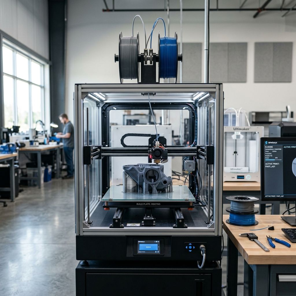
The Elegoo Centauri Carbon establishes a rugged desktop manufacturing platform engineered specifically around high-temperature polymers and fiber-reinforced composites. Operating abrasive filaments like PA-CF, PET-CF, and PC-GF at high volumetric deposition rates accelerates wear across mechanical, thermal, and kinematic sub-assemblies. This industrial field guide details preventative lifecycle thresholds, metrology-driven diagnostic criteria, and precise workshop replacement protocols for all critical wear components on the Centauri Carbon.
CRITICAL WORKSHOP SAFETY PROTOCOL: THERMAL & ELECTRICAL HAZARDS
Always isolate the printer from mains power (110V/230V AC) and allow the chamber, heatbed, and toolhead to cool to ambient room temperature (<35°C) prior to disassembling drive gearboxes or belt drive structures. For hotend service operations requiring thermal torque application, maintain tool insulation rated to 300°C and wear heat-resistant nitrile-lined Kevlar safety gloves to mitigate instantaneous contact burns and catastrophic high-temperature short-circuits.
1. Lifecycle Thresholds & Component Degradation Metrics
Under continuous industrial utilization, component degradation follows distinct abrasive wear and fatigue regimes governed by material composition, print velocity, and ambient chamber temperatures. Fiber-filled composites exert continuous mechanical abrasion against all filament contact surfaces, while high-velocity CoreXY acceleration produces cyclic strain across drive belts and pulleys.
To establish rigorous maintenance schedules, workshop operators must monitor Mean Time Between Failures (MTBF) and wear rates benchmarked across standard neat polymers versus abrasive engineering filaments. When comparing these wear factors to open-gantry architectures such as the Prusa MK4S & MK4 Common Issues and Fixes, enclosed CoreXY systems concentrate thermal energy within the chassis, requiring dedicated inspection of polymer idlers and active filtration canisters.
| Sub-Assembly Component | OEM Specification / Material | Standard Polymer MTBF (Hours) | CF/GF Composite MTBF (Hours) | Fastener Torque Spec (Nm) |
|---|---|---|---|---|
| Hotend Nozzle | Hardened Steel / Bi-Metal 0.40mm | 1,200 – 1,500 hrs | 250 – 350 hrs | 2.5 ± 0.2 Nm (@ 285°C) |
| Dual-Drive Extruder Gears | Surface-Nitrided Tool Steel HRC 60+ | 2,000 – 2,500 hrs | 500 – 700 hrs | 0.8 Nm (M2.5 Case Screws) |
| CoreXY Synchronous Belts | Gates 2GT 6mm Neoprene Fiberglass Core | 3,000 hrs | 2,200 hrs | 1.8 Nm (Tensioner Brackets) |
| PTFE Filament Guide Liners | Virgin PTFE / ID 2.0mm × OD 4.0mm | 800 hrs | 150 – 200 hrs | Friction-fit Collet Clip |
| Activated Carbon Air Filter | Cylindrical Pelletized Virgin Carbon | 600 hrs (VOC saturation) | 400 hrs (Styrene / Amide load) | Twist-Lock Bayonet |
2. Hotend Assembly & Hardened Steel Nozzle Replacement
The standard hotend on the Elegoo Centauri Carbon employs a wear-resistant hardened nozzle seated directly against an integrated bi-metal heatbreak. When processing carbon-fiber filaments, microscopic fiber fragments shear against the nozzle orifice and internal taper, creating asymmetric bore erosion, internal flow turbulence, and erratic die swell. Similar phenomena are thoroughly analyzed in our field study on X1-Carbon Nozzle Clogging: Causes and Fixes.
ENGINEERING CAUSE-EFFECT: VOLUMETRIC EXTENSION & BORE EROSION
Abrasive fibers cause non-uniform mechanical cavitation at the nozzle tip. As the orifice expands from 0.40mm to 0.48mm, the backpressure within the melt zone drops precipitously, disrupting steady-state flow dynamics. Volumetric deposition rate is calculated as:
Q = v × w × h [mm³/s]
Where v is toolhead translation speed, w is extrusion trace width, and h is slice layer height. When internal orifice diameter increases due to abrasive degradation, dynamic pressure loss produces uncontrolled oozing, localized layer delamination, and stringing. Recalibrate your printing profiles using our dedicated Flow Rate Calculator to verify actual volumetric throughput against rated melt-chamber limits.
Step-by-Step Nozzle Disassembly and Hot-Tightening Protocol
- Unload Filament and Purge Chamber: Heat the hotend to 250°C, retract any loaded filament cleanly through the reverse Bowden tube, and purge residual melt pool material using high-temperature cleaning filament or unfilled nylon.
- Expose Heater Block Assembly: Power down the system, allow temperatures to drop to room temperature, and remove the magnetic front faceplate and toolhead cooling shroud by loosening the two retaining screws on the side housing. Gently detach the high-RPM radial part cooling fan JST connector.
- Pre-Heat for Thermal Release: Power the machine on and raise nozzle temperature to 285°C via the firmware console. Never attempt cold removal of the nozzle, as thread-locking polymer resins and coefficient of thermal expansion mismatches will shear the heatbreak throat.
- Torque Counter-Hold: Secure the rectangular heater block using an insulated 12mm workshop spanner or specialized parallel-jaw wrench. Do not allow rotational torque to transfer to the slender heatbreak neck.
- Extract Worn Nozzle: Using an insulated 6mm hex socket wrench, turn the nozzle counter-clockwise. Once cracked loose, back it out cleanly onto a heat-resistant silicone mat. Inspect the mating face for filament carbonization.
- Install Replacement Nozzle: Hand-thread the new hardened steel nozzle clockwise into the heater block until finger tight against the internal throat interface. Ensure a visible gap of 0.5mm to 1.0mm remains between the nozzle hex shoulder and the bottom of the heater block.
- Final Hot-Torquing: Set the calibrated workshop torque wrench to exactly 2.5 Nm. Stabilize the heater block with the 12mm spanner and torque the nozzle until the wrench clicks. Power off immediately and allow ambient cooling before replacing the silicone insulation sock.
3. Direct-Drive Extruder Hardened Gearbox Rebuild
The Centauri Carbon utilizes a high-torque dual-drive planetary reduction system. Over hundreds of operational hours with abrasive composite strands, the micro-hobbed teeth encounter continuous frictional shear. This conforms to Archard's classical abrasive wear formulation:
W = K × (F_N × s) / H
Where W represents volumetric material loss, K is the dimensionless abrasive wear coefficient, F_N is normal clamping force exerted by the extruder tension spring, s is cumulative linear filament distance traversed, and H is the Vickers surface hardness of the hobbed gear steel. Once the nitrided surface layer degrades, tooth engagement slips, creating micro-underextrusions and inconsistent wall thicknesses.
- Tooth Crest Rounding: Visual inspection under 10x magnification reveals loss of sharp tooth crests on primary drive gear.
- Composite Swarf Accumulation: Debris compacted inside tooth valleys restricts filament penetration depth below the critical 0.15mm threshold.
- Drive Shaft Needle Bearing Play: Radial play exceeding 0.05mm requires immediate bearing replacement along with gear set.
- Tension Arm Micro-Cracking: Inspect the spring-loaded idler hinge for cyclic fatigue cracking around the pivot pin.
Extruder Teardown and Gear Replacement Procedure
To overhaul the dual-drive gearbox, remove the three M2.5 socket-head cap screws securing the stepper motor to the extruder chassis. Carefully pull the motor rearward to disengage the main drive pinion. Unseat the idler tension thumbscrew and capture the compression spring. Extract the primary and secondary drive gears along with their miniature flanged needle roller bearings.
Clean all residual carbon dust from the gear pocket using non-chlorinated solvent or isopropyl alcohol (99.8%). Press the replacement nitrided steel gears onto their precision ground pins, ensuring the dual meshing spurs align with zero backlash. Apply a pinhead-sized droplet of synthetic fluoropolymer grease (Krytox GPL 205) exclusively to the drive spur teeth; ensure the filament-gripping hobbed grooved tracks remain completely free of lubrication. Reassemble and adjust spring tension so that neat filament exhibits crisp, shallow indentations without dimensional crushing.
4. CoreXY Synchronous Belt Drive Replacement & Tuning
The kinematics of the Elegoo Centauri Carbon depend on two continuous Gates 2GT 6mm synchronous timing belts operating in an interwoven planar configuration. Belt degradation manifests as elastomeric tooth shear, internal fiberglass tensile cord stretch, and edge fraying caused by misalignment against smooth idler flanges. Readers seeking a deep technical dive into pulley runout and concentricity should consult our industrial guide on Replacement Timing Pulleys: A Field Guide to Belt Drive Precision.
Belt Replacement Protocol
- Loosen the rear tensioner locking bolts on both left and right gantry tensioner assemblies to relieve tensile load on both the A and B loops.
- Unclamp the belt anchor teeth located within the toolhead carriage clamps. Withdraw the old belts through the gantry corner idlers and motor pulleys.
- Cut two equal lengths of genuine Gates 2GT 6mm neoprene belts (fiberglass-reinforced, not steel-core, to prevent low-bend radius cord fatigue over small idler diameters).
- Thread the new belt loops through the respective pulleys, confirming that belt teeth seat squarely inside pulley grooves without twisting along the runs.
- Anchor the lead ends into the toolhead clamp with equal tooth engagement, maintaining symmetrical tail lengths on both sides.
ACOUSTIC TENSION CALIBRATION: FREQUENCY FORMULATION
Accurate CoreXY belt synchronization requires matching the natural fundamental resonant frequencies of both the A and B belt spans over a fixed geometric span length. Resonance is defined by the transverse string equation:
f = (1 / (2 × L)) × √(T / μ)
Where f is resonant frequency (Hz), L is unsupported span length (m), T is static belt tension (N), and μ is linear mass density of the 2GT belt (approximately 0.0084 kg/m for 6mm width). Park the toolhead at center-front (X=125mm, Y=0mm). Pluck the rear horizontal belt span and measure acoustic frequency using a digital frequency sensor. Adjust tensioner thumb-bolts until both belt paths resonate at exactly 110 Hz ± 3 Hz (corresponding to ~55 N static tension). Verify gantry perpendicularity using our 3D Printer Troubleshooting Matrix.
5. Enclosure Air Filtration: VOC & Carbon Filter Replacement
Processing engineering polymers like ABS, ASA, and carbon-reinforced polyamides emits volatile organic compounds (VOCs, specifically styrene monomer and caprolactam) alongside sub-micron particulate matter (UFPs). The Centauri Carbon incorporates an active recirculation and exhaust filtration canister. Over time, physical adsorption pores within the activated carbon bed reach chemical saturation.
Replace the carbon canister every 400 to 600 print hours, or immediately upon detecting faint organic odor signatures outside the enclosure during high-temperature printing cycles. Disengage the quarter-turn bayonet filter holder on the rear inner chamber wall. Discard the exhausted cartridge into commercial waste according to local chemical handling regulations. Seat the fresh OEM carbon cartridge, verifying that the silicone sealing gasket compresses evenly against the bulkhead housing to prevent bypass airflow.
6. Post-Replacement Verification & Recalibration Checklist
- Mechanical Clearance Check: Move the toolhead manually across the full X/Y envelope (0 to 250mm) to verify zero binding, friction spikes, or belt rubbing.
- Heater Cartridge & Thermistor Integrity: Verify cold resistance (approx. 100kΩ at 25°C for NTC thermistor, ~12Ω across 50W 24V heater cartridge).
- PID Tuning Cycle: Execute automated PID auto-tune at target operational temperature (285°C hotend, 100°C bed) using M303 commands to prevent thermal oscillation.
- Resonance Frequency Sweep: Execute input shaping accelerometer calibration to map updated modal resonance peaks after belt tensioning.
- First-Layer Z-Offset Cal: Run inductive probe Z-offset compensation to account for microscopic nozzle length variance (±0.12mm) following hot tightening.
7. Frequently Asked Questions (Workshop Troubleshooting & GEO)
Can I use brass or standard copper nozzles on the Elegoo Centauri Carbon?
Brass nozzles should never be used with composite filaments as abrasive fibers enlarge the bore within 50 print hours; always install hardened steel, tungsten carbide, or diamond-tipped nozzles for abrasive polymers.
Why does filament leak above the heater block after nozzle replacement?
Leakage above the heater block occurs when the nozzle is tightened cold or bottoms out against the block shoulder instead of seating firmly against the heatbreak; re-torque to 2.5 Nm at 285°C leaving an inspection gap.
How often should CoreXY belts be retensioned on the Centauri Carbon?
Inspect belt resonance after the initial 50-hour bedding-in period, and retension every 500 operating hours to maintain symmetrical 110 Hz acoustic tension and avoid dimensional ghosting.
Related Intel
QIDI Plus 4 vs X-Max 3: Shop Comparison and ROI
The QIDI Plus 4 introduces a dual-heater 65°C chamber and 305x305x280mm volume, whereas the older X-Max 3 delivers a larger 325x325x315mm envelope but suffers from slower chamber ramp rates and bulkier gantry mass.
Kobra 2 Max Y-Axis Problems and Community Fixes
Flat spots on SG15 bearings, carriage flex, and pulley tooth shear cause Y-axis artifacts on the Kobra 2 Max. Fixes: lubricate rails, reduce acceleration, and check belt tension.
Fixing Kinematic Binding on RatRig V-Core 3.1
RatRig V-Core 3.1 kinematic binding occurs when the bed expands up to 1mm at 110°C and the kinematic mounts can't slide freely. Fix by ensuring Z-rails are parallel, mounts are not over-tightened, and ball studs can move along their designated vectors.