Fixing Gantry Racking on Creality K1C and K2 Pro

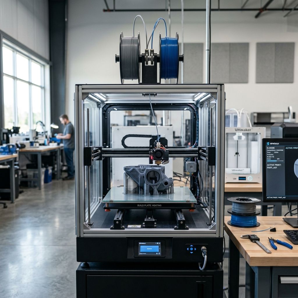
Creality K2 Pro & K1C Field Troubleshooting: The No-Nonsense Shop Guide
Two hundred hours of continuous high-temp printing on a Creality K1C or K2 Pro will tell you more about its structural shortcuts than any glossy marketing brochure. Here is how we keep these CoreXY workhorses squared, cleared, and operational under real shop-floor conditions.
At a Glance: Shop-Floor Diagnostic Baseline
This technical log focuses on structural alignment, thermal stability, and mechanical wear points. If you are chasing down erratic extrusion issues, run through our 3D Printer Troubleshooting tool before tearing down your toolhead assembly.
We have run the K1C and the K2 Pro through various production cycles, chewing through carbon fiber-filled filaments, high-speed PLA, and abrasive materials. While these machines offer highly competitive speed-to-cost ratios, they suffer from common engineering trade-offs. The lighter gantry assemblies, quick-swap "Unicorn" integrated nozzles, and high-temp chambers present unique failure modes under constant vibration and heat. To minimize down-time, we have cataloged the top three physical failures we encounter on the shop floor, along with the precise diagnostic and repair procedures required to keep them running.
For context on factory-level issues before making a purchasing decision, read our breakdown of Common Creality K2 Pro and K1C Failures, which outlines out-of-the-box discrepancies.
Failure 1: Gantry Racking & Belt Tension Imbalance
On any CoreXY printer, gantry squareness is the foundation of dimensional accuracy. When the belts are unevenly tensioned, the X-axis carriage loses its perpendicularity to the Y-axis rails. This is known as "racking." On both the K1C and the K2 Pro, the factory belt tensioners can slip over time, or the belts themselves stretch unevenly. Under high acceleration (often exceeding 15,000 mm/s²), an out-of-square gantry causes severe ghosting, diagonal ovality in circular holes, and premature wear on the linear bearings.
The Physics of Belt Tension and Resonance
To diagnose belt issues scientifically, we use the fundamental frequency of the belt span. When you pluck a belt, it acts as a vibrating string. We can calculate the required tension using the classical string frequency formula:
Formula:
f = (1 / (2 * L)) * sqrt(T / μ)
Where:
- f = Fundamental frequency of the belt span (Hz)
- L = Free span length of the belt being plucked (meters)
- T = Belt tension (Newtons)
- μ = Linear mass density of the belt (for standard 6mm Gates-style 2GT belts, this is approximately 0.009 kg/m)
Let's do a real-world shop calculation. Suppose we isolate a free span length (L) of exactly 0.35 meters on the K1C gantry. We are aiming for a target tension (T) of approximately 58 Newtons to keep the gantry stiff without overloading the stepper motor bearings. Let's calculate the target frequency we need to measure with our microphone or acoustic analyzer:
Calculation:
T = 58 N
L = 0.35 m
μ = 0.009 kg/m

f = (1 / (2 * 0.35)) * sqrt(58 / 0.009)
f = (1 / 0.70) * sqrt(6444.44)
f = 1.428 * 80.27
f ≈ 114.6 Hz
To optimize performance, adjust your belts until both left and right spans register at approximately 115 Hz when plucked at an identical 0.35m span. If they differ by more than 5 Hz, your gantry will rack during rapid direction changes.
Step-by-Step Gantry Squaring & Tensioning Workflow
Do not trust the self-tensioning spring screws entirely; they often bind or settle over time. Use this manual calibration method instead:
- Release Tension: Power down the machine. Loosen the tensioning locking screws on the rear left and right corners of the printer frame. Allow the internal springs to push against the tension pulleys, but do not lock them yet.
- Align the Gantry: Push the X-axis gantry all the way to the rear of the frame. Ensure that both the left and right gantry blocks make firm, flush contact with the rear corner brackets simultaneously. If one side hits while the other has a gap, your gantry is racked.
- Lock and Square: Clamp or hold both sides of the gantry tightly against the rear frame corners. While holding them square, manually tighten the tensioner adjustment screws to adjust the belt frequency to the target 115 Hz (or your machine's specific target).
- Secure the Locking Screws: Once the frequencies are matched on both the left and right belts, tighten the locking bolts to prevent the tensioner blocks from shifting under high-acceleration loads.
- Run Calibration: Boot the machine and execute the input shaper calibration. Compare the resulting X and Y axis resonance graphs. If you see clean, single-peak curves, your belts are balanced. If you see multi-peaked, messy curves, you still have mechanical slop or asymmetric belt tension.
- Target X-Axis Tension: 110 Hz to 120 Hz (measured at 350mm span)
- Target Y-Axis Tension: 110 Hz to 120 Hz (measured at 350mm span)
- Allowable Skew Tolerance: < 0.1 mm over a 200mm square travel
- Recommended Inspection Cycle: Every 150 printing hours
Failure 2: The "Unicorn" Quick-Swap Nozzle Clogs & Heat Creep
The K1C and K2 Pro utilize an integrated all-metal "Unicorn" nozzle design where the hardened steel tip, copper alloy body, and titanium throat are fused into a single assembly. While this design prevents leaks between the nozzle and the heatbreak, it has a major vulnerability: heat creep in fully enclosed chambers, especially when printing low-temp materials like PLA or PETG with the door shut and lid on.
The Anatomy of a Unicorn Clog
Because the copper heat-sink block has limited surface area and relies on a high-RPM compact cooling fan, the thermal transition zone can creep upward if the chamber temperature exceeds 40°C. When printing PLA, the filament softens prematurely in the titanium throat. Once it swells, the direct-drive extruder gears lose traction, shaving the filament and creating a complete jam.
If you are pushing the limits of speed or dialing in specialized flow rates to prevent backpressure in the hotend, check out our guide on Creality K1C and K2 Pro Calibration Tips to align your extrusion profiles with your mechanical hardware limits.
The Cold-Pull Cleardown Procedure (Modified for Unicorn Hotends)
Because of the integrated design, standard cleaning needles can damage the internal polished transition zone of the titanium throat. When a jam occurs, use this modified cold-pull procedure:
- Heat the Hotend: Set the nozzle temperature to 250°C. Ensure any remaining filament in the extruder is unclamped by releasing the extruder tension lever.
- Insert Cleaning Filament: Manually feed a piece of high-viscosity cleaning filament (or nylon) into the top of the toolhead. Push it down by hand until some material extrudes from the nozzle tip. If it is completely jammed, use a 1.5mm brass rod to carefully push the blockage through while the hotend is at 260°C.
- Cool Down Under Pressure: Set the hotend temperature to 0°C. Continue to apply light downward pressure on the cleaning filament until the temperature drops below 130°C. This ensures the filament packs tightly into the nozzle tip and throat cavities, grabbing any burnt debris or carbon-fiber residue.
- Execute the Cold Pull: Once the temperature reaches 90°C (for Nylon) or 80°C (for PLA), flip the extruder lever to the open position. Grasp the filament firmly with pliers and pull straight up with a swift, steady motion.
- Inspect the Plug: The pulled filament should show a perfect inverse mold of the nozzle interior, including the narrow nozzle tip and the wider transition throat. If the plug is dirty, repeat the process until the pulled plastic is completely clean.
Tech Alert: Never attempt a cold pull on a Unicorn nozzle below 70°C. The mechanical force required can bend the delicate titanium heatbreak tube or damage the load-cell sensor assembly mounted directly below the toolhead carriage.
Failure 3: First-Layer Inconsistencies and Strain-Gauge Thermal Drift
Both the K1C and K2 Pro feature strain-gauge or load-cell-based automatic bed leveling systems. When the nozzle touches the bed, the sensor measures the resistance change to calculate the exact Z-height. This system should theoretically yield a perfect first layer every time without manual offset tuning. However, we consistently see first-layer drift where the nozzle either scrapes the build plate or prints too high, leading to bed adhesion failures.
The Cause: Thermal Expansion & Hysteresis
The strain sensors are highly sensitive to thermal fluctuations. If you start your bed leveling cycle immediately after turning on the bed heater, the aluminum build plate, magnetic sheet, and the load cells themselves are still actively expanding. A bed set to 100°C for ABS will take up to 15 minutes to reach thermal equilibrium, even if the thermistor reads 100°C after 3 minutes. This thermal lag causes the load sensors to drift during the probing sequence, skewing the mesh data.
The Solution: The Thermal Soak Protocol
To eliminate first-layer drift, you must integrate a thermal soak period into your start G-code. This ensures all components have stabilized before the nozzle probes the bed.
Add this customized start G-code macro to your slicer profile:
M140 S[bed_temperature] ; Start heating the bed
M104 S150 ; Heat nozzle to 150C (non-ooze standby temp to prevent plastic drool)
G28 ; Home axes
G1 Z50 F3000 ; Lift nozzle to mid-chamber
M190 S[bed_temperature] ; Wait for bed to reach target temp
G4 S600 ; Enforce a 10-minute (600 seconds) thermal soak delay
G29 ; Execute bed mesh leveling now that frame is thermally stable
M109 S[nozzle_temperature] ; Heat nozzle to final print temp
- Target Soak Time (PLA/PETG): 5 to 8 Minutes
- Target Soak Time (ABS/ASA/PA-CF): 12 to 15 Minutes
- Maximum Allowable Mesh Variance: 0.2 mm across entire bed
- Nozzle Pre-Probe Temperature: 140°C - 150°C (prevents plastic drops on bed)
Extruder Gear Backlash and Maintenance
The direct-drive extruder utilizes a dual-gear system to grab filament. Over time, plastic debris, carbon fiber dust, and metal-on-metal wear degrade the performance of these gears. If you notice irregular extrusion lines or fine extrusion pulses (VFA), the culprit is likely backlash or debris buildup in the gear teeth.
The Mechanics of Gear Backlash
When the dual extruder gears mesh, there must be a tiny clearance (backlash) to prevent binding, but too much clearance causes rotational slop during retractions. This manifests as blobs at the start of a layer line or gaps after a retraction move. Additionally, carbon-fiber particles act as an abrasive, grinding down the hardened teeth and reducing the effective drive diameter.
Preventive Maintenance Log
To prevent premature gear wear and keep the filament path running smoothly, we recommend checking these baseline specs during your scheduled maintenance:
- Extruder Gear Material: Hardened Steel (dual-drive)
- Backlash Tolerance: < 0.05 mm
- Drive Tension Screw: 1.5 turns in from first thread contact (PLA/PETG)
- Cleaning Interval: Clean gear teeth with a brass wire brush every 50 hours of CF printing
Step-by-Step Extruder Cleaning & Tension Adjustment
- Disassemble the Housing: Power off the machine. Remove the three M2.5 screws holding the plastic toolhead cover. Unplug the hotend cooling fan connector to clear your workspace.
- Expose the Extruder Gears: Remove the tension spring screw and pull the tension arm back to expose the dual drive gears.
- Brush Clean: Use a stiff brass wire brush to clean out any filament debris lodged in the gear teeth. Avoid using steel wire brushes, as they can dull the sharp grip profiles of the teeth.
- Inspect for Wear: Look for any flattening of the gear teeth under a magnifying glass. If the teeth are rounded or show shiny wear marks, replace the gear set immediately to prevent filament slippage.
- Lubricate the Needle Bearings: Apply a tiny drop of synthetic grease (like Super Lube) to the needle bearings inside the idler gear. Do not get grease on the filament-gripping teeth. If grease gets on the teeth, clean it off using isopropyl alcohol (IPA).
- Reassemble and Adjust Tension: Put the housing back together. Tighten the tension screw until it makes contact with the spring, then turn it 1.5 full rotations clockwise. For soft filaments like TPU, back it off half a turn to prevent flattening the filament profile.
Frequently Asked Questions
Why does my K1C / K2 Pro display a "Heater Timeout" or "T0 Sensor Error" during prints?
This is usually caused by a loose connection at the toolhead breakout board. The constant vibration of fast CoreXY movements can loosen the JST-style connectors on the hotend heater and thermistor lines, causing temporary resistance spikes that trigger the safety firmware.
What is the correct chamber temperature limit to prevent PLA clogs?
To print PLA reliably without heat creep, keep your chamber temperature below 35°C. Keep the front door open and remove the top glass lid entirely to allow heat to escape from the build plate.
How do I fix the high-frequency vibration/humming on the K2 Pro at specific speeds?
This humming is typically a structural resonance of the frame or gantry panels. You can isolate this issue by printing rubber dampening feet for the machine frame and adjusting your slicer settings to avoid printing at speeds that excite these resonance frequencies (often between 120mm/s and 150mm/s).
Troubleshooting Matrix
| Observed Symptom | Probable Root Cause | Immediate Corrective Action |
|---|---|---|
| First layer has rough, wavy ridges or gouges into the build plate. | Thermal drift on the strain gauges or leftover plastic residue on the nozzle tip during probing. | Clean the nozzle tip at 200°C before probing, and add a 10-minute bed thermal soak to your start G-code. |
| Severe ringing/ghosting along the X-axis but clean along the Y-axis. | Loose X-axis belt or mechanical play in the toolhead carriage bearings. | Verify X-belt tension (target 115Hz) and inspect the linear carriage guide for play or carriage wobble. |
| Extruder skips steps (clicking sound) during high-flow prints. | The print speed exceeds the volumetric flow limit of the Unicorn nozzle, or the nozzle temperature is too low. | Increase print temperature by 10°C, or reduce your maximum volumetric flow rate in your slicer. |
| Parts are physically skewed or out of square when printed. | The X and Y axes are racked out of square due to asymmetric belt tension. | Loosen both tensioners, push the gantry flat against the rear corners, and re-tension the belts evenly. |
Critical Torque Spec: When replacing the integrated Unicorn nozzle, never tighten it cold. Always heat the hotend to 240°C and use a calibrated torque wrench set to exactly 1.5 Nm. Over-tightening when hot will snap the thin titanium throat, while under-tightening will lead to molten filament leaking past the threads during high-pressure extrusion cycles.
Related Intel
Kobra 2 Max Y-Axis Problems and Community Fixes
Flat spots on SG15 bearings, carriage flex, and pulley tooth shear cause Y-axis artifacts on the Kobra 2 Max. Fixes: lubricate rails, reduce acceleration, and check belt tension.
Fixing Kinematic Binding on RatRig V-Core 3.1
RatRig V-Core 3.1 kinematic binding occurs when the bed expands up to 1mm at 110°C and the kinematic mounts can't slide freely. Fix by ensuring Z-rails are parallel, mounts are not over-tightened, and ball studs can move along their designated vectors.
Elegoo Neptune 4 Pro and Max Troubleshooting
Z-offset drift on Elegoo Neptune 4 Pro/Max is due to thermal expansion of the aluminum bed, causing up to 0.4 mm height change. Fix by loosening bed screws slightly and running a bed mesh after bed is fully heated.