Creality K2 Pro & K1C Settings: High-Speed CoreXY Tuning

* Affiliate Disclosure: We may earn a commission from qualifying purchases made via our verified links at no additional cost to you.
The Industrial Maker is reader-supported. When you purchase equipment, parts, or materials through links on our site, we may earn an affiliate commission at no additional cost to you.
Creality K2 Pro & K1C Kinematic Optimization: CoreXY Resonance Tuning, High-Flow Hotend Rheology, and Enterprise Production Profiles
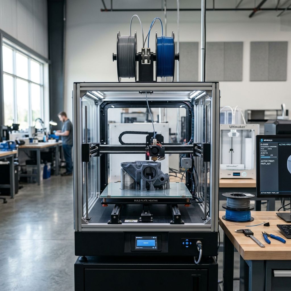
In high-throughput rapid prototyping and additive contract manufacturing, the Creality K-series flagship platforms—the enclosed Creality K1C and the expansive Creality K2 Pro featuring the CFS (Creality Filament System)—represent a significant architectural pivot toward enterprise CoreXY performance. Engineered to achieve print speeds up to 600 mm/s and accelerations exceeding 20,000 mm/s², these machines rely on lightweight toolheads, integrated input-shaping accelerometers, closed-loop stepper motor control, and rigid die-cast aluminum chassis.
However, running high-performance polymers (carbon-fiber reinforced polyamides, polycarbonate, and flame-retardant ABS) at true industrial speeds exposes fundamental physical trade-offs. Without rigorous calibration of belt tension harmonics, dynamic pressure advance, volumetric melt flow boundaries, and chamber thermal gradients, high-speed CoreXY kinematics quickly degrade part tolerances, induce non-planar layer ringing, and cause catastrophic extruder heat creep. This engineering manual provides manufacturing engineers, print farm technicians, and tooling specialists with empirical formulas, machine telemetry parameters, and step-by-step diagnostic workflows required to maximize throughput while maintaining DIN ISO 2768-m dimensional compliance.
Recommended Hardware: Creality K2 Pro & K1C
Check current stock, real-time pricing, and official replacement parts directly on Amazon:
View on Amazon • Check Live Price →1. CoreXY Kinematic Architecture & Belt Resonance Calibration
The kinematic foundation of both the K1C and K2 Pro is a stacked dual-belt CoreXY mechanism driven by dual high-torque stepper motors positioned at the rear frame corners. The carriage position () is governed by coupled orthogonal transformations:
Where and denote the displacement vectors of the primary drive belts. In a CoreXY architecture, any differential in belt tension () directly distorts the toolhead perpendicularity under high dynamic jerk. If belt tension is asymmetric, a commanded 90° contour vector deflects into a parallelogram, producing oval internal bores and asymmetric surface ringing.
ENGINEERING CALCULATION: COREXY BELT TENSION & RESONANCE FREQUENCY
1. Transverse Vibrational String Mechanics:
The natural resonant frequency of a tensioned timing belt over a free span length is governed by the classical string equation:
Where:
- is the static tensile force within the belt (Newtons, ).
- is the linear mass density of the 6 mm GT2 fiberglass/Kevlar-reinforced chloroprene belt (typically ).
- is the unconstrained measurement span (meters, ). On the K1C and K2 Pro, parking the toolhead at the center front bed yields an unconstrained span (150 mm).
To establish the target factory belt tension of per belt, solve for frequency :
Practical Workshop Rule: When measuring via acoustic spectrum analyzer apps or microphone stroboscopes across a 150 mm span, tune both A and B belt adjusters until fundamental peak frequencies match identically between 110 Hz and 115 Hz for standard shop operation, with less than 2 Hz delta between belts.
Dynamic linear speeds can be cross-verified using our official Print Speed Calculator.
Following belt equalization, run the automated resonance sweep via Klipper Fluidd/Mainsail or Creality OS. The onboard ADXL345 toolhead accelerometer measures vibrational decay across sweeping input frequencies from 10 Hz to 120 Hz. For optimal surface finish:
-
X-Axis Shaper Selection: Target Shaper =
MZVorEIat resonant frequency . This suppresses ringing while permitting max acceleration of without motor stalling. -
Y-Axis Shaper Selection: Target Shaper =
MZVor2HUMP_EIat resonant frequency . Due to the higher mass of the cross-gantry assembly, dampening requirements are higher on the Y-axis. - Gantry Orthogonality Verification: Print a single-perimeter square gauge. Measure opposing diagonals (). Gantry skew must not exceed . If deviation is higher, loosen gantry idler bracket fasteners, square the physical carbon-rod gantry against the rear frame stops, and re-torque.
- Input Shaper Damping Ratio (): Ensure configured damping ratio is maintained at to prevent excessive corner smoothing and radius erosion on sharp edges.
2. Thermal Rheology: The Unicorn Nozzle & Volumetric Flow Limits
The Creality K1C and K2 Pro utilize Creality's unified "Unicorn" quick-swap nozzle assembly. Unlike traditional threaded nozzle systems where the heatbreak and brass nozzle meet at an internal mechanical joint, the Unicorn architecture integrates a hardened steel tip, a copper conduction sleeve, and a titanium-alloy heatbreak into a continuous, hermetically sealed structure. This eliminates internal molten filament leaking between nozzle and heatbreak threads while reducing thermal barrier thermal resistance.
However, running high-speed extrusion demands rigorous adherence to volumetric flow physics. The maximum linear print speed for any given layer height and line width is fundamentally constrained by the melt zone's volumetric flow limit :
If commanded volumetric throughput exceeds , back-pressure in the melt pool exceeds the traction torque of the dual-gear extruder, triggering immediate stepper motor skip (clicking) and intermittent layer starvation. For deep structural insights on melt pool dynamics, see our analysis on Industrial Slicer Architecture: Mesh Diagnostics, ArcWelder Kinematics, and Melt Pressure Equations.
| Material Grade | Nozzle / Bed Temp (°C) | Melt Viscosity | Max Volumetric Flow () | Max Safe Speed (0.2h / 0.42w) |
|---|---|---|---|---|
| Hyper PLA / High-Speed PLA | 220°C / 55°C | Low (Pseudoplastic shear thinning) | 30 - 32 mm³/s | 350 - 380 mm/s |
| PETG / PETG-ESD | 250°C / 75°C | Medium-High | 20 - 22 mm³/s | 230 - 250 mm/s |
| ABS / ASA Industrial | 265°C / 100°C | Medium | 24 - 26 mm³/s | 280 - 300 mm/s |
| PA-CF (Nylon Carbon Fiber) | 285°C / 85°C | High (Short fiber suspension) | 16 - 18 mm³/s | 180 - 200 mm/s |
| TPU 95A Elastomer | 230°C / 45°C | Very High (Viscoelastic drag) | 6 - 8 mm³/s | 60 - 85 mm/s |
To calculate exact throughput thresholds for customized line widths and layer heights, benchmark your spool using our interactive Flow Rate Calculator and match cooling demands using our Layer Height Calculator.
3. Pressure Advance & Dynamic Extrusion Calibration
Due to the elastic compliance of filament along the reverse Bowden tube path and the compressibility of the semi-solid polymer column within the heat zone, dynamic pressure lags behind linear stepper velocity. When decelerating into corners, nozzle pressure remains elevated, resulting in heavy corner seams and exterior surface bulging.
The mathematical model implemented in Creality OS (Klipper fork) calculates additional instantaneous extrusion position via the linear relation:
Where is the Pressure Advance factor (seconds, ) and is toolhead linear velocity.
SHOP FLOOR ALERT: PREVENTING HEAT CREEP & EXTRUDER STRIPPING
Enclosure Thermal Management Protocol: When printing low-glass-transition polymers like standard PLA ( to ) on the K1C or K2 Pro, the internal chamber temperature must NOT exceed 38°C. Continuous radiant heat from a 60°C heated bed inside a fully sealed chamber causes ambient air to exceed PLA's softening point before the filament reaches the drive gears.
This triggers filament flattening, dual-drive gear slipping, and severe nozzle throat jamming. Always unlatch the top tempered glass cover or prop open the front door when executing long PLA production cycles. If clogs occur, reference our 3D Printer Troubleshooting Guide.
To calibrate Pressure Advance on K-series extruders:
- Line Method Test: Execute the Klipper PA calibration pattern (
TUNING_TOWER COMMAND=SET_PRESSURE_ADVANCE PARAMETER=ADVANCE START=0 FACTOR=0.002). Inspect printed test bands under magnification. - Direct-Drive Values: For the K1C/K2 Pro dual-gear direct drive with Unicorn nozzle, standard baseline PA values are:
- Hyper PLA: to
- PETG: to
- PA-CF: to
- ABS/ASA: to
- Smooth Time Tuning: Keep
pressure_advance_smooth_timeconfigured at 0.040s (default Klipper value). Lowering below 0.020s causes violent instantaneous extruder stepper acceleration spikes, resulting in missing micro-steps.
4. Creality Filament System (CFS) Multi-Material Tuning & Purge Optimization
The Creality K2 Pro introduces the CFS multi-material management unit, handling automated spool switching, active RFID filament identification, and sealed desiccant/heated moisture protection. Operating a 4-channel CFS in an industrial production environment requires minimizing purge waste and cycle latency during toolhead filament swaps.
Every filament retraction cycle follows a sequence of 6 mechanical phases: toolhead cutter blade engagement, reverse Bowden retraction to the CFS buffer, selector barrel indexing, forward feed of target material, nozzle pre-melting, and high-pressure cavity purge. In multi-color or multi-material assemblies, uncalibrated purge volumes can multiply overall print time by 300% and generate more waste scrap than net part weight.
- Tip Shaping & Ramming Optimization: Configure slicer ramming sequence with a 1.2s ramp-down duration at prior to cut activation. This shapes a clean flat filament tip, preventing stringy tails from catching on the internal PTFE couplers during retraction.
- Differential Purge Matrix: Never use a static flush volume. Configure dynamic volumetric purging based on pigment and polymer chemistry. Light-to-dark transitions (e.g., White to Black) require only , while dark-to-light transitions (Black to Natural/White) require to prevent chromatic bleeding.
- Filament Drying Requirements: PA-CF and PVA support materials absorb atmospheric moisture rapidly. Use our dedicated Filament Drying Calculator to compute chamber soak cycles before initiating long multi-material runs.
- Flush-into-Infill Activation: In Creality Print or OrcaSlicer, enable "Flush into object's infill" and "Flush into object's support". For solid engineering housings, this recovers up to 60% of purged resin directly into internal structural infill cells without affecting external dimensional or cosmetic quality.
To evaluate machine depreciation, purge loss, and overall batch production economics, assess your production runs using our Cost Calculator. For head-to-head architectural comparisons against competitor enclosed platforms, examine our benchmark on Bambu Lab X1-Carbon & X1E vs Prusa MK4S: Head-to-Head Industrial Engineering Review and Shop ROI.
5. Production Slicer Profiles & Acceleration Envelopes
To achieve reliable tolerances on mechanical assemblies (press-fit bearings, threaded bosses, and mating snap-fits), apply the following validated kinematic envelopes in Creality Print, OrcaSlicer, or PrusaSlicer. To evaluate open-source g-code automation strategies, review our guide to PrusaSlicer Enterprise: Industrial Profiles, Toolpath Math, and Print Farm G-Code Automation or compare motion controller dynamics in Sovol SV08 & SV08 Max: Klipper Errors and Workshop Fixes.
| Slicer Parameter | Ultra-Speed Prototype (PLA) | Structural Functional (ABS/PETG) | Precision Engineering (PA-CF) |
|---|---|---|---|
| Outer Wall Speed | 200 mm/s | 120 mm/s | 80 mm/s |
| Inner Wall Speed | 300 mm/s | 200 mm/s | 140 mm/s |
| Sparse Infill Speed | 400 mm/s | 250 mm/s | 160 mm/s |
| Max Print Acceleration | 15,000 mm/s² | 10,000 mm/s² | 6,000 mm/s² |
| Outer Wall Acceleration | 8,000 mm/s² | 5,000 mm/s² | 3,000 mm/s² |
| Retraction Distance / Speed | 0.6 mm @ 45 mm/s | 0.8 mm @ 40 mm/s | 0.8 mm @ 35 mm/s |
| Chamber Fan Speed | 100% (Exhaust venting) | 0% - 20% (Heat retention) | 0% (Heated chamber soak) |
6. Frequently Asked Questions (Creality K-Series Tuning)
What causes the K1C / K2 Pro extruder to click and skip steps during first layer infill?
Extruder clicking during broad first layers is typically caused by excessive bed leveling offset compensation forcing the nozzle too close to the PEI sheet, creating extreme hydrodynamic back-pressure that stalls the dual-drive gears. Increasing Z-offset by +0.02 mm to +0.04 mm restores the required clearance and relieves nozzle back-pressure.
Why is belt frequency calibration on CoreXY more critical than on Cartesian bedslingers?
In Cartesian kinematics, the X and Y axes are completely mechanically decoupled. In CoreXY, both A and B belts simultaneously control both X and Y motions; any difference in belt tension induces orthogonal skewing, rotating the toolhead coordinate frame and resulting in asymmetric resonance artifacts and non-perpendicular corners.
Can the Unicorn nozzle assembly be cold-pulled to clear carbonized fiber debris?
Yes. Heat the nozzle to 250°C with Nylon filament loaded, allow it to cool down to 90°C under slight manual downward pressure, and then perform a rapid vertical pull. The monolithic Unicorn heatbreak design prevents molten plastic from leaking into thermal threads, making atomic cold pulls exceptionally effective.
How should support structures be configured for high-speed industrial prints?
Tree (organic) supports with branch angles set to 45° and 2 perimeter walls provide superior dynamic stability against high-acceleration toolhead vibrations compared to standard rectilinear support columns. Calculate exact support interface configurations with our Supports Calculator.
Related Intel
Bambu Lab P1S & P1P Common Problems: Workshop Fixes
Comprehensive engineering root-cause analysis and troubleshooting guide for Bambu Lab P1S and P1P 3D printers. Addresses high-incidence workshop failures including AMS PTFE capstan friction binding, extruder filament cutter jamming, carbon rod bearing slurry build-up, toolhead cover detachment, and enclosure heat creep clogs. Features mathematical formulations for Euler-Eytelwein capstan tube friction and CoreXY belt harmonic resonance tuning, backed by actionable maintenance procedures and diagnostic matrices.
Best Materials for Creality K2 Pro & K1C: Industrial Filament Guide
Definitive materials selection and thermal processing guide for the Creality K2 Pro and K1C high-speed CoreXY 3D printers. Evaluates fiber-reinforced polymers (PA-CF, PET-CF, PC-CF), engineering thermoplastics (ASA, ABS, Polycarbonate), and high-flow flexibles. Includes mathematical formulations for thermal shrinkage strain, peel moment crystallization stress, and hotend volumetric throughput ceilings. Features comprehensive rheological parameter tables, hygroscopic pre-drying protocols, and enclosure heat management guardrails for zero-delamination industrial manufacturing.
Bambu Lab P1S vs P1P: Slicer & Hardware Comparison
Head-to-head engineering and software evaluation of the Bambu Lab P1S versus P1P CoreXY 3D printers. Analyzes enclosure thermal equilibrium thermodynamics, MC board auxiliary cooling, high-temperature composite processing (ABS, ASA, PA-CF), and software ecosystem differences across Bambu Studio, OrcaSlicer, and PrusaSlicer. Features an exhaustive workshop ROI model, failure rate metrics, and a definitive procurement verdict for commercial prototyping shops.