Measuring Engineering Polymers with Fowler Electronic Tools

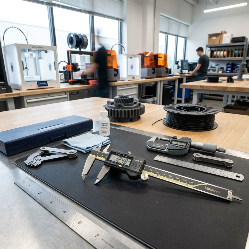
Measuring Engineering Polymers with Fowler Electronic Tools
Dimensional verification of high-performance thermoplastic parts requires accounting for contact compliance, jaw flex, and thermal expansion mismatch between hardened steel anvils and polymer substrates.
Metrology Architecture & Material Compliance Note
Verifying dimensional tolerances on additive and machined polymer components presents a fundamental metrological challenge: mechanical compliance. When utilizing the Fowler Electronic Tools Set—specifically digital calipers and micrometers with hardened stainless steel anvils—the measuring force applied by the operator directly deforms the polymer substrate. For semi-crystalline thermoplastics like PA12, POM-C, and PEEK, this contact compliance induces non-linear measurement drift between 15 µm and 45 µm if jaw closure force is not strictly standardized. Calibrate slicer scaling matrices using our Layer Height Calculator alongside physical anvil verification.
The Mechanics of Polymer Measurement with Digital Hand Tools
Machinists accustomed to alloy steels and 6061 aluminum often make severe measurement errors when transitioning to engineering polymers. A Fowler digital caliper delivers a display resolution of 0.01 mm (0.0005 in) with an instrumental repeatability spec of 0.01 mm. However, transferring that measurement accuracy onto an unfilled polyoxymethylene (POM-C) flange or an additive polyetheretherketone (PEEK) bracket is rarely a plug-and-play operation. Hand tools rely on operator feel, and in polymer metrology, operator feel translates directly into uncontrolled jaw pressure.
Steel exhibits an elastic modulus of approximately 200 to 210 GPa, meaning standard caliper jaw closure forces (typically 3 N to 8 N depending on thumb wheel torque) generate negligible elastic strain on metallic workpieces. In contrast, unfilled thermoplastics possess elastic moduli ranging from 1.2 GPa to 3.8 GPa. When clamping a 3 mm thin-walled boss using the flat outside jaws of a Fowler caliper, the contact stress quickly exceeds the elastic threshold of the polymer skin, yielding readings that under-measure the true nominal dimension by tens of microns. In production batches, this manifests as parts being scrapped for being out-of-spec when they actually sit dead-center in the design tolerance band.
Hertzian Contact Stress and The Physics of Jaw Indentation
To quantify the true error introduced during hand-tool inspection, we analyze the contact mechanics between the Fowler ground stainless steel jaw and a cylindrical polymer specimen. We model the interface using the classical Hertzian line contact formulation for two parallel elastic cylinders, where one cylinder represents the radius of the caliper jaw edge (effectively an anvil with edge radius R1 = 50 mm) and the second represents a round polymer rod (radius R2 = 12.5 mm).
The effective equivalent elastic modulus E* is defined by the elastic moduli and Poisson ratios of the contact pair:
1 / E* = (1 - ν1²) / E1 + (1 - ν2²) / E2
Where:
- E1 = 205 GPa (Fowler hardened stainless steel anvil)
- ν1 = 0.28 (Tool steel Poisson ratio)
- E2 = 2.80 GPa (Unfilled Polyamide 66 at 50% relative humidity)
- ν2 = 0.40 (Polymer Poisson ratio)
Calculating the steel compliance factor:
(1 - 0.28²) / 205 GPa = 0.9216 / 205 = 0.0045 GPa⁻¹
Calculating the polymer compliance factor:
(1 - 0.40²) / 2.80 GPa = 0.8400 / 2.80 = 0.3000 GPa⁻¹
Summing the components gives 1 / E* = 0.3045 GPa⁻¹, yielding an effective modulus E* of 3.28 GPa. Notice that the compliance of the steel anvil contributes less than 1.5% to the total deformation; the polymer deformation dominates the metrological error.
Now, calculate the half-width b of the rectangular contact patch under a moderate caliper closure force F = 5.5 N distributed over a contact engagement length L = 6.0 mm (force per unit length w = 0.917 N/mm):
b = √[ (4 · w · R*) / (π · E*) ]
With equivalent radius R* = (R1 · R2) / (R1 + R2) = (50 · 12.5) / 62.5 = 10.0 mm:
b = √[ (4 · 0.917 N/mm · 10 mm) / (π · 3284 N/mm²) ] = √[ 36.68 / 10317 ] = √[ 0.003555 ] = 0.0596 mm (59.6 µm)
The resulting total elastic indentation displacement δ at the center of the contact line is calculated through the relative approach formula:
δ ≈ (w / (π · E*)) · [ 2 · ln(4 · R* / b) - 1 ]
Substituting the values:
δ ≈ (0.917 / 10317) · [ 2 · ln(4 · 10 / 0.0596) - 1 ] = 0.0000889 mm · [ 2 · ln(671.1) - 1 ]
Since ln(671.1) ≈ 6.509, we have [ 2 · 6.509 - 1 ] = 12.018.
δ ≈ 0.0000889 mm · 12.018 = 0.00107 mm (1.07 µm)
While an indentation of 1.1 µm on a solid cylinder appears manageable, the situation shifts dramatically when measuring hollow bosses or thin-wall FDM shells. A 1.2 mm wall section under 5.5 N experiences bending deflection and localized shell ovalization exceeding 28 µm. When paired with inexperienced technicians who push the thumb roll with up to 15 N of force, the measured dimension collapses by more than 0.08 mm. This dwarfs the 0.02 mm accuracy specification of the tool itself.
Thermal Mismatch: The Silent Tolerance Killer
The second primary failure mode in shop-floor polymer inspection is thermal expansion mismatch. Machining shops and inspection bays rarely operate at a pristine 20.0 °C (68 °F) reference temperature. In typical workshop environments, ambient temperatures fluctuate between 18 °C in winter mornings and 28 °C during mid-afternoon production runs.
Tool steel has a coefficient of linear thermal expansion (CLTE) of roughly 10.5 to 11.5 × 10⁻⁶ K⁻¹. Engineering thermoplastics have CLTE values an order of magnitude higher:
- PTFE: 120 to 140 × 10⁻⁶ K⁻¹
- POM-C (Acetal): 100 to 110 × 10⁻⁶ K⁻¹
- Unfilled PA6/PA12: 80 to 95 × 10⁻⁶ K⁻¹
- PEEK (Unfilled): 45 to 50 × 10⁻⁶ K⁻¹
- Carbon-Fiber Filled PEEK (along flow axis): 15 to 22 × 10⁻⁶ K⁻¹
Consider a 120 mm POM-C bushing turned on an industrial lathe and measured immediately after machining when the core temperature rests at 32 °C. The technician measures the outer diameter using a Fowler digital caliper acclimated to the 22 °C tool bench. The thermal differential calculation is straightforward:
ΔL_error = L0 · [ α_polymer · (T_part - T_ref) - α_steel · (T_tool - T_ref) ]
With L0 = 120 mm, T_ref = 20 °C, T_part = 32 °C, T_tool = 22 °C:
Part expansion = 120 mm · 110 × 10⁻⁶ K⁻¹ · (32 - 20) K = 120 · 0.000110 · 12 = 0.1584 mm
Tool expansion = 120 mm · 11 × 10⁻⁶ K⁻¹ · (22 - 20) K = 120 · 0.000011 · 2 = 0.0026 mm
Net dimensional bias = +0.1558 mm (+156 µm).
If the technician adjusts the CNC tool offset based on this reading, the part will shrink by 0.156 mm as it cools to room temperature, instantly falling under the lower tolerance limit. When handling high-CLTE engineering polymers, thermal soak periods are mandatory. Parts must sit on an aluminum equalization plate in the metrology room for at least 45 minutes prior to final verification.
Engineering Material Compatibility and Measurement Limits
The following matrix outlines structural metrics, thermal expansion rates, and recommended tool configurations across common engineering polymers evaluated with the Fowler Electronic Tools Set:
| Polymer Type | Elastic Modulus (GPa) | CLTE (µm/m·K) | Max Jaw Pressure (N) | Deflection at 5N (µm) | Recommended Fowler Tool |
|---|---|---|---|---|---|
| PEEK (Unfilled) | 3.8 | 47 | 6.5 | 0.8 | Electronic Micrometer (Friction Thimble) |
| PEEK-CF30 (30% Carbon) | 7.5 | 18 | 10.0 | 0.3 | Digital Caliper with Carbide Tipped Jaws |
| POM-C (Acetal Copolymer) | 2.8 | 110 | 4.0 | 1.4 | Digital Caliper (Thumb Wheel Disengaged) |
| Nylon PA12 (Dry As-Printed) | 1.7 | 105 | 3.5 | 2.9 | Electronic Micrometer with Ratchet Stop |
| Nylon PA66 (Conditioned 50% RH) | 1.4 | 90 | 2.5 | 3.8 | Optical Comparator or Low-Force Caliper |
| Polycarbonate (PC) | 2.3 | 65 | 5.0 | 1.6 | Digital Caliper (Standard Jaws) |
| PTFE (Virgin) | 0.5 | 135 | 1.0 | 14.5 | Non-Contact Optical / Fowler Depth Probe with Disc Base |
| Ultem 9085 (PEI) | 3.2 | 55 | 5.5 | 1.1 | Digital Caliper / Depth Micrometer |
Metrological Principles: Mitigating Abbe Error and Jaw Deflection
Ernst Abbe established that maximum measurement accuracy is only achieved when the measurement scale lies along the exact same line as the axis of measurement. Outside micrometers conform to Abbe’s principle; calipers do not. On a Fowler digital caliper, the measuring jaws extend 40 mm away from the internal capacitive glass scale embedded in the stainless steel beam.
This physical offset creates an unavoidable Abbe error whenever force is exerted on the tips of the jaws:
E_Abbe = d_offset · tan(θ)
Where d_offset is the distance from the beam to the contact point, and θ is the angular play or elastic flex of the sliding jaw on the main beam. Even on a perfectly adjusted Fowler slide where the gib screws have been carefully set, clearances of 0.005 mm across the 16 mm carriage width produce an angular tilt of approximately 0.018 degrees (0.000314 radians). At the extreme tip of the 40 mm jaws:
E_Abbe = 40 mm · 0.000314 ≈ 0.0125 mm (12.5 µm).
If an inspector measures a soft polymer part near the jaw tips while pushing hard on the thumb roll, jaw tilt and polymer indentation compound. The combined error routinely reaches 0.035 mm to 0.050 mm. For consistent results, technicians must always position the workpiece as close to the main beam as geometry allows, reducing d_offset to under 10 mm and cutting Abbe error by 75%.
- Jaw Tip Flex Error: 12 µm to 18 µm when force exceeds 6 N at 35 mm jaw extension.
- Beam Clearance Slop: 0.004 mm to 0.008 mm carriage float; requires weekly brass gib readjustment.
- Capacitive Sensor Dirt Limit: Particles above 15 µm cause 5 mm digital read jumps; clean with isopropyl alcohol only.
- Anvil Parallelism Spec: 0.005 mm over 40 mm contact length; verify with grade 0 ceramic gage blocks.
- Operating Temperature Band: 18 °C to 24 °C; outside this band, differential thermal drift exceeds 0.01 mm per 50 mm length.
- Recommended Battery Cell: Silver Oxide SR44 (1.55V); do NOT use alkaline LR44 due to rapid voltage sag below 1.35V.
Anisotropic Shrinkage and Slicer Compensation in Additive Parts
In modern industrial facilities utilizing additive manufacturing alongside traditional CNC machining, the Fowler Electronic Tools Set is the first line of defense in validating anisotropic print shrinkage. High-temperature materials such as PEEK, PEKK, and carbon-reinforced polyamides do not shrink uniformly in three dimensions. The deposition process aligns molecular chains along the raster lines (X and Y axes), while inter-layer bonding (Z axis) experiences distinct cooling gradients and thermal contraction.
When measuring test coupons printed on industrial platforms, we consistently record anisotropic shrinkage differentials. For a 50 mm nominal cube printed in PA12-CF:
- X-axis (raster direction): 49.88 mm (0.24% shrinkage)
- Y-axis (transverse raster): 49.76 mm (0.48% shrinkage)
- Z-axis (layer stacking): 49.62 mm (0.76% shrinkage)
For operations deploying workshop tool sets across print farms, implementing structured tool management protocols is vital. Review our field notes on Deploying 3D Printing Tool Sets in Commercial Farms to standardize measurement procedures across machine operators.
To accurately capture Z-axis shrinkage without flattening layer ridges, use the Fowler Electronic Depth Micrometer rather than caliper outside jaws. The wide flat base of the depth micrometer bridges across multiple layer lines, establishing an averaged reference plane rather than settling into a microscopic layer groove. For comprehensive structural evaluations of commercial additive hardware, examine our analysis of the Creality K2 Pro vs K1C Structural Analysis.
Hygroscopic Swelling in Polyamides: The Moisture Variable
One of the most frustrating workshop scenarios occurs when a batch of Nylon parts passes inspection on Friday afternoon, only to fail incoming inspection at the client’s facility on Tuesday morning. Polyamides (PA6, PA66, and to a lesser extent PA12) are notoriously hygroscopic. They absorb ambient moisture from atmospheric humidity until reaching equilibrium moisture content.
For unfilled PA6, moisture absorption at 50% relative humidity averages 2.5% to 3.0% by weight, expanding the physical volume and increasing linear dimensions by 0.5% to 0.7%. On a 50 mm precision bore, that represents an expansion of 0.25 mm to 0.35 mm. When using the internal measuring jaws of a Fowler caliper on a freshly machined or sintered nylon part, the technician is measuring a transient state. Unless the part is sealed in a moisture barrier bag immediately after machining, or conditioned to equilibrium humidity before final inspection, the numbers logged on the Fowler display are meaningless for long-term assembly fits.
Data Output and SPC Integration on the Shop Floor
Modern quality assurance demands complete traceability. The Fowler Electronic Tools Set features direct SPC (Statistical Process Control) data output ports. Connecting the Fowler digital indicator or micrometer to an SPC interface cable allows operators to capture dimensional readings directly into quality control databases with a single footswitch tap.
This automated data transfer eliminates two massive sources of human error in high-mix manufacturing: transposition mistakes (such as typing 24.51 mm instead of 24.15 mm) and subjective operator rounding. Furthermore, real-time charting reveals tool wear trends on CNC turning centers cutting abrasive glass-filled polymers long before parts exceed the upper specification limit.
Workshop Failure Points and Preventive Maintenance
Even premium metrology hand tools suffer degradation in abrasive workshop environments. Polymer chips, coolant mists, and fine carbon fiber dust present distinct threats to electronic measuring instruments:
First, carbon fiber dust generated during post-processing of CF-PEEK or CF-Nylon is electrically conductive and highly abrasive. If carbon dust settles inside the sliding carriage of a digital caliper, it causes micro-scratching on the glass scale grid and bridges the capacitive copper tracks. This manifests as random display freezes, erratic negative numbers, or sudden 5.08 mm (0.200 in) incremental jumps. Always wipe the beam with a lint-free cloth dampened with 99% isopropyl alcohol before and after every shift. Never blow compressed air into the carriage; this forces fine carbon particles directly past the rubber wiper seals and into the sensor head.
Second, monitor the gib adjustment screws on the top edge of the caliper slider. Over months of rapid sliding, the brass gib strip settles, allowing lateral wobble. To set the gib tension: loosen the two locking screws, gently turn the adjustment set-screws clockwise until slight resistance is felt on the thumb roll, then back off one-eighth of a turn. The slider should glide smoothly across the entire 150 mm travel without catching and without detectable rocking play when gripped by hand.
Frequently Asked Questions
How can I avoid crushing soft polymers when using a Fowler digital caliper?
Disengage the thumb roll and close the jaws using light finger contact on the sliding frame, or switch to a Fowler electronic micrometer equipped with a calibrated ratchet stop or friction thimble limited to 5 N to 10 N.
Why does my Fowler caliper display jump by random values when measuring carbon-fiber parts?
Airborne carbon fiber dust has entered the capacitive sensor gap between the slider and the glass beam scale, creating electrical bridging that disrupts capacitive phase tracking.
Should I calibrate my Fowler digital tools against steel gage blocks when inspecting plastic parts?
Yes, always verify zero and linearity using certified steel or ceramic gage blocks at 20 °C, but apply analytical mathematical offsets for polymer contact compliance and thermal coefficient mismatch.
Why are silver oxide SR44 batteries required instead of cheaper alkaline LR44 cells?
Alkaline cells have a sloping voltage discharge curve that drops below the 1.35V logic threshold of the capacitive ASIC under low temperatures, causing intermittent sensor calculation dropouts.
Critical Workshop Metrology Alert
Never leave Fowler digital calipers stored with the measuring jaws fully closed and locked. Thermal expansion cycles will force the ground measuring faces against each other under continuous static load, introducing localized contact stress, jaw burrs, and microscopic deformation of the internal sliding mechanism. Always store instruments in their fitted case with jaws opened 1 mm to 2 mm and the thumbscrew loosened.