xTool M1 Ultra Buying Guide: Shop Floor Reality

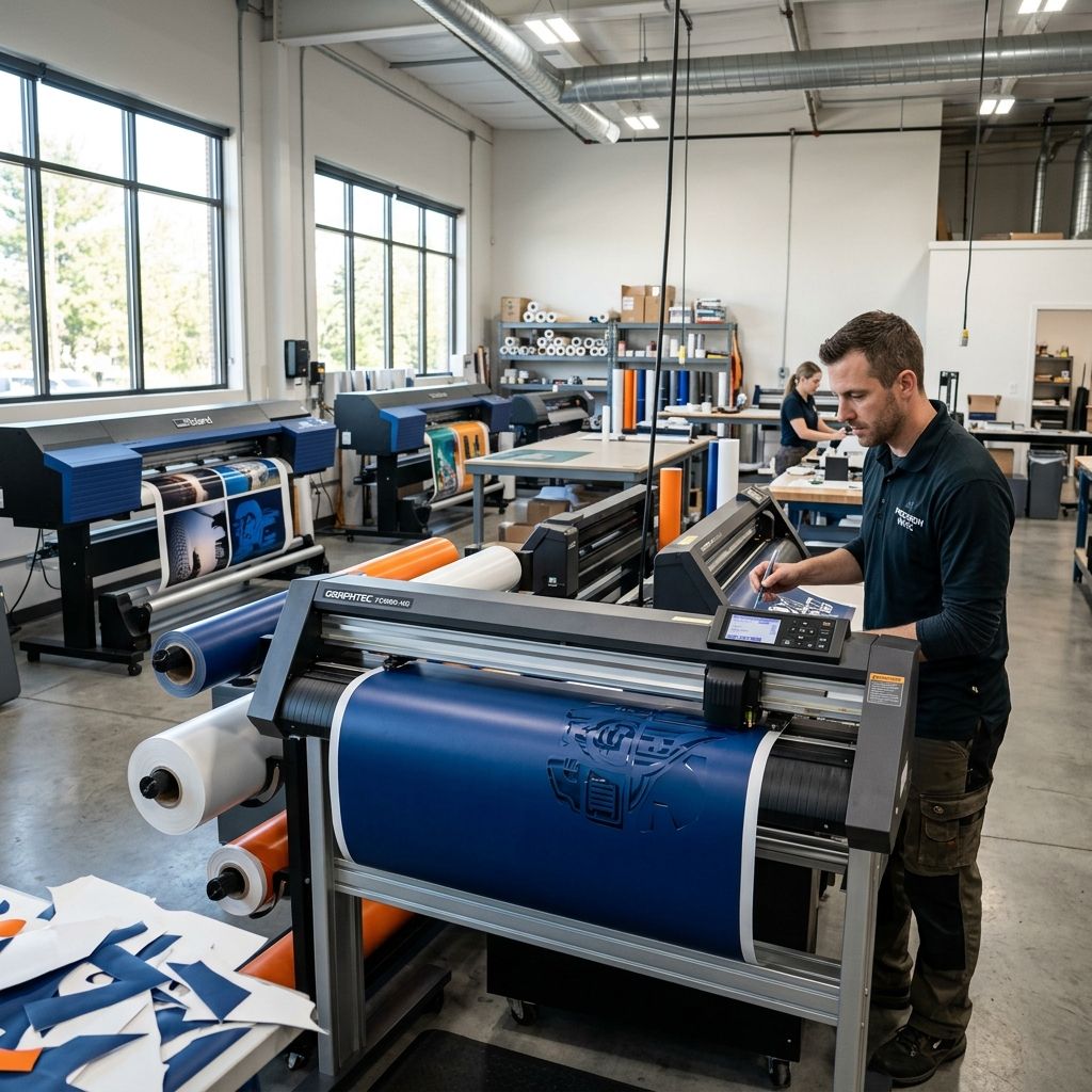
xTool M1 Ultra Buying Guide: Shop Floor Reality
An exhaustive operational teardown of the 4-in-1 desktop workstation: laser diode physics, drag knife mechanics, thermal inkjet limits, and true production ROI.
Shop Floor Assessment
The xTool M1 Ultra consolidates four distinct fabrication modes—diode laser processing (10W or 20W optical output), blade cutting (drag, rotary, and foil scoring), thermal inkjet color printing, and pen drawing—into a single enclosed desktop footprint measuring 620 x 498 x 178 mm with an active work area of 300 x 300 mm. For small custom job shops, design labs, and prototype studios handling mixed-media personalization, this unit eliminates the footprint of three separate benchtop machines. However, consolidation introduces unavoidable mechanical compromises: shared gantry dynamics limit laser acceleration to moderate thresholds, blade downforce caps at 500 grams, and thermal inkjet printheads require strict isolation from airborne laser aerosols. Use our Cost Calculator to compute hourly depreciation against dedicated single-process hardware before committing production hours.
Kinematic Architecture and Toolhead Exchange Dynamics
The core chassis of the M1 Ultra utilizes an extruded aluminum baseplate coupled with stamped sheet steel side uprights, providing adequate torsional rigidity for light-duty benchtop tasks. Unlike industrial gantry systems that mount precision-ground linear profile rails on all axes, the M1 Ultra implements a dual-steel cylindrical guide rail on the X-axis carriage, driven by a closed-loop GT2 neoprene timing belt with a 2 mm pitch. The Y-axis gantry is driven symmetrically by dual stepper motors through synchronized timing belts along the lateral frame channels.
Positional resolution is governed by 1.8-degree bipolar stepper motors operating under 1/16 microstepping drivers, yielding a theoretical Cartesian resolution of 0.01 mm. In actual workshop verification, linear mechanical backlash settles between 0.04 mm and 0.07 mm under moderate feed rates (100 to 160 mm/s). When operating in non-contact laser mode, inertia remains predictable because the toolhead mass is fixed at roughly 450 grams for the 20W diode package. However, switching to contact cutting with the drag knife introduces lateral tool deflection against dense substrates such as 0.8 mm magnetic sheet or 24-ounce vegetable-tanned leather.
The physical toolhead exchange relies on a mechanical dovetail clamp secured by a manual quick-release lever, coupled with a multi-pin gold-plated pogo connector for digital signaling and power delivery. In high-frequency rotation shops where operators alternate between laser marking, knife cutting, and inkjet passes within a single job, the pogo pin array demands routine wiping with laboratory-grade anhydrous isopropyl alcohol. Residual airborne soot from wood ablation coats the electrical landing pads over time, inducing intermittent serial communication drops if neglected.
Optical Performance: 10W vs 20W Diode Ablation Physics
The optical module employs gallium nitride (GaN) semiconductor laser diodes emitting at a nominal center wavelength of 455 nm (visible blue spectrum). The 20W variant packages four individual 5.5W diode emitters whose raw beams are compressed via micro-lenses, combined through spatial polarization beam-splitters, and directed through a final telecentric plano-convex focusing optic. This yields a compressed rectangular focal spot measuring approximately 0.08 mm along the X-axis by 0.10 mm along the Y-axis at a standard focal distance of 40 mm.
Because the 455 nm wavelength couples effectively with organic polymers, lignins, paper, and dark anodized aluminum, the system ablates non-metallic organic surfaces with high efficiency. However, physical reality dictates strict optical boundaries that marketing literature routinely glosses over:
- Wavelength Transmission Trap: The 455 nm blue beam passes directly through transparent, translucent, and light blue cast acrylic without significant absorption. The energy cannot couple into the polymer chain, resulting in localized melting, boiling, or zero cut penetration. True optical fabrication of clear acrylic requires a 10,600 nm CO2 tube or a 1,064 nm fiber source.
- Beam Astigmatism Asymmetry: The rectangular beam footprint means kerf width differs by roughly 25% depending on whether a vector cuts along the X or Y travel path. High-precision mechanical press-fits (such as finger joints in 3 mm birch) must be pre-compensated in CAD to account for this non-circular kerf profile.
- Depth of Field Restrictions: With a numerical aperture optimized for a tight 0.08 mm waist, the effective Rayleigh range (depth of focus where spot diameter remains under 1.41 times waist diameter) is roughly 2.2 mm. Cutting materials thicker than 4 mm requires manual Z-axis step-downs between subsequent passes to reposition the beam waist inside the cut channel.
Physics of Failure: Diode Energy Density and Thermal Soak Calculation
When cutting wood composites or thick acrylics on a diode laser, the primary failure mode is thermal charring, edge flaring, and localized ignition caused by excessive thermal diffusion into the surrounding substrate. Understanding this requires calculating the peak optical irradiance ($I$) and comparing the linear energy input against the thermal diffusivity of the workpiece.
The peak optical irradiance ($I$) delivered by the 20W optical diode array across its focal spot area is calculated as:
Spot area ($A$):
$$A = \frac{\pi}{4} \cdot d_x \cdot d_y = \frac{\pi}{4} \cdot (0.008\text{ cm}) \cdot (0.010\text{ cm}) = 6.283 \times 10^{-5}\text{ cm}^2$$
Peak irradiance ($I$):
$$I = \frac{P_{optical}}{A} = \frac{20\text{ W}}{6.283 \times 10^{-5}\text{ cm}^2} \approx 318,300\text{ W/cm}^2$$
While an irradiance of 3.18 x 10^5 W/cm^2 vaporizes surface lignins instantly, the linear heat input per unit length ($Q_L$) depends directly on travel feed rate ($v$):
$$Q_L = \frac{P_{optical}}{v}$$
Consider cutting 3 mm Baltic birch plywood with a thermal diffusivity $\alpha \approx 1.8 \times 10^{-7}\text{ m}^2/\text{s}$. If an operator sets a slow single-pass feed rate of $v = 3\text{ mm/s}$ ($0.003\text{ m/s}$):
$$Q_L = \frac{20\text{ J/s}}{3\text{ mm/s}} \approx 6.67\text{ J/mm}$$
At 6.67 J/mm, the exposure duration per spot diameter ($t_{dwell} = \frac{0.08\text{ mm}}{3\text{ mm/s}} \approx 26.7\text{ ms}$) drastically exceeds the thermal relaxation time of thin lignin fibers. Heat conducts outward laterally, raising the kerf boundary to over 400 degrees Celsius, pyrolyzing the formaldehyde binder, and widening the kerf from 0.09 mm to over 0.24 mm with heavily charred, brittle edges.
In contrast, running two successive passes at $v = 8\text{ mm/s}$ with an auxiliary coaxial air assist delivering 25 PSI yields:
$$Q_L = \frac{20\text{ J/s}}{8\text{ mm/s}} = 2.50\text{ J/mm per pass}$$
The dwell time drops to 10 ms per pass. High-pressure air ejects melted and vaporized particulates immediately from the cut channel before heat conducts laterally. The resulting kerf width holds steady at 0.095 mm +/- 0.01 mm, and edges display clean, caramelization-free profiles ready for adhesive bonding.
Mechanical Tooling: Drag Knife Offset, Rotary Blades, and Downforce Calibration
The mechanical cutting bay is where the M1 Ultra separates itself from conventional laser-only frames. It accommodates a standard swivel drag blade (30-degree, 45-degree, and 60-degree cemented carbide inserts), a motorized rotary textile blade, and a rounded foil embossing/scoring stylus. The mechanical carriage utilizes an internal voice-coil / stepper actuator providing programmable downforce ranging from 10 grams to 500 grams in 5-gram increments.
Operating a drag knife differs fundamentally from optical beam processing because the blade tip does not rotate on center. Instead, the carbide cutting edge trails the central pivot axis by an eccentric mechanical offset distance ($r_{offset}$), typically 0.25 mm for the bundled 45-degree blade.
When the toolpath executes an abrupt corner transition through angle $\theta$, the uncompensated tip traces an inward circular arc rather than a sharp vertex. The theoretical path deviation ($\Delta s$) without corner overcut compensation is calculated as:
$$\Delta s = r_{offset} \cdot \sqrt{2 \cdot (1 - \cos\theta)}$$
For an orthogonal 90-degree vector corner ($\theta = 90^\circ$):
$$\Delta s = 0.25\text{ mm} \cdot \sqrt{2 \cdot (1 - 0)} = 0.25 \cdot 1.4142 \approx 0.354\text{ mm}$$
If the slicing software (xTool Creative Space) has its blade offset parameter misconfigured by even 0.05 mm, the blade fails to close vector loops on adhesive vinyl. The operator experiences weeding tears where small lettering remains connected to surrounding waste vinyl. Calibrating the drag blade requires cutting a series of 10 mm concentric test squares, examining corner squareness under a 10x shop loupe, and fine-tuning the offset value until corner loops terminate cleanly without hook ears or rounded filleting.
For technical textiles, woven fiberglass, and stretchy ballistic nylon, the rotary cutter eliminates the lateral dragging friction that causes adhesive vinyl mats to bunch up. The motorized rotary disk rolls over the fibers, distributing shear load downward against the self-healing cutting bed mat rather than dragging fibers along the travel vector.
Thermal Inkjet Printing: Capabilities, Substrate Chemistry, and Resin Contamination
The M1 Ultra incorporates a multi-color thermal inkjet cartridge system capable of printing direct-to-substrate graphics at up to 600 DPI resolution. The cartridge slides into an auxiliary carrier alongside the primary toolhead, allowing users to print full-color graphics on light wood veneers, raw leather, canvas, and uncoated cardstock, then immediately cut the contour using the laser or drag blade.
However, running inkjet mechanics inside a chassis that also performs laser ablation introduces severe workshop hazards that require rigid procedural discipline:
- Aerosol Soot Deposition: Laser ablation of wood, acrylic, or leather produces dense smoke laden with sticky, acidic resin condensates. If the inkjet cartridge remains seated during an extended 30-minute laser cutting job without vigorous extraction, aerosol resin coats the cartridge orifice plate. The microscopic nozzle bores (roughly 20 to 30 microns in diameter) clog permanently once exposed to heat and airborne soot.
- Substrate Absorption Limits: The CMY aqueous dye-based ink lacks UV photoinitiators or solvent carriers. On porous, untreated hardwoods like basswood or poplar, ink bleeds along longitudinal grain capillaries, softening graphic edges. On non-porous materials like acrylic or powder-coated aluminum, the ink beads immediately due to surface tension mismatch and wipes off with casual contact unless a pre-coat primer is hand-applied.
- Execution Sequence Protocol: Operators must always execute the print phase FIRST on pristine, soot-free substrates. Once printing completes, cap and stow the ink cartridge in its moisture-sealed dock before engaging the laser or air assist.
Comprehensive Specifications: Hybrid Workstation vs Dedicated Tooling
To evaluate where the xTool M1 Ultra fits into an active engineering workshop or light production space, inspect its verified physical parameters against typical dedicated single-function shop machines:
| Subsystem / Parameter | xTool M1 Ultra Specification | Shop Floor Practical Capability |
|---|---|---|
| Laser Optical Power | 10W or 20W GaN Diode (455 nm) | Cuts up to 6 mm basswood; surface marks anodized metal; cannot cut clear acrylic |
| Laser Spot Dimensions | 0.08 x 0.10 mm (Elliptical) | High detail raster engraving; 0.095 mm kerf with 25 PSI auxiliary air assist |
| Mechanical Working Area | 300 x 300 mm (11.8 x 11.8 in) | Fits 12x12 in craft stock; tight for standard 12x24 in industrial sheet goods |
| Maximum Z-Axis Travel | 125 mm (with riser base) / 25 mm standard | Accommodates rotary chuck attachments for tumblers up to 100 mm diameter |
| Blade Tooling Options | Fine-point drag, rotary cutter, foil tip | Cuts vinyl, foil, thin leather, paper; rotary blade handles woven fabrics cleanly |
| Maximum Blade Downforce | 500 grams (programmable) | Sufficient for 24 oz cardstock and HTV; underpowered for rigid 1.5 mm gaskets |
| Inkjet Print Resolution | 300 x 600 DPI (Aqueous Dye CMY) | Crisp graphics on porous untreated wood and cardstock; requires primer on metal |
| Max Travel Speed | 400 mm/s vector / raster | Practical cutting speed: 4-12 mm/s; practical engraving speed: 120-200 mm/s |
| Exhaust Ducting | Internal 60 mm blower (approx 35 CFM) | Inadequate for indoor use without high-flow external centrifugal exhaust fan |
| Software Interface | xTool Creative Space (XCS) | Streamlined multi-tool sequencing; LightBurn support limited to laser mode |
Tooling Strengths and Production Bottlenecks
Every hybrid machine trades peak specialized throughput for functional versatility. The operational pros and cons reflect real-world workshop usage over hundreds of production hours:
- Pro: Unified Alignment Coordinate System: Because the laser, camera, drag blade, and inkjet printhead share the exact same gantry datum, contour-cutting pre-printed graphics or laser-engraving cut vinyl achieves sub-0.2 mm registration without manual workpiece re-clamping.
- Pro: Bench Space Conservation: Replaces a 24-inch vinyl cutter, a desktop diode laser, and a specialized flatbed direct printer, preserving roughly 2.5 square meters of premium bench space in small labs.
- Pro: Comprehensive Safety Enclosure: The filtered Class 1 acrylic cover blocks 455 nm scatter radiation, while magnetic interlock switches kill the diode beam instantly when the lid is lifted during active operation.
- Con: Slow Batch Processing Speed: A dedicated 50W CO2 laser cuts 6 mm wood at five times the linear feed rate of the 20W diode. A dedicated servo-driven vinyl plotter cuts intricate sign vinyl at 800 mm/s versus the M1 Ultra's 150 mm/s practical limit.
- Con: High Risk of Cutting Mat Destruction: Forgetting to swap out the adhesive vinyl cutting mat before running a high-power laser vector cut will instantly incinerate the PVC/TPE mat, creating hazardous hydrogen chloride vapors and ruining the sticky bed.
- Con: Proprietary Consumables Ecosystem: The custom inkjet cartridges and proprietary blade holders carry higher per-unit replacement costs than standard third-party Roland-style blade holders or bulk refill inks.
Preventive Maintenance and Wear Component Protocol
To sustain repeatable tolerances and prevent premature component failure under daily workshop cycling, adhere to the following maintenance routine:
- Exhaust Fan Impeller De-tarring (Every 25 Operating Hours): Pop off the rear exhaust plenum shroud. Scrub the internal blower wheel blades with citrus-based solvent or mineral spirits to remove gummy wood tar. Unbalanced tar buildup causes high-frequency chassis vibration that translates directly into visible wavy ripples on engraved vector boundaries.
- X-Axis Linear Guide Lubrication (Every 50 Operating Hours): Clean the dual stainless cylindrical rods with a lint-free wipe. Apply four drops of light synthetic machine oil (ISO VG 32 or synthetic PTFE-infused lubricant). Cycle the carriage manually across the 300 mm span to distribute the oil film evenly. Never use WD-40 or thick wheel-bearing grease, which attracts airborne sawdust.
- Diode Optical Window Inspection (Weekly): Unthread the protective brass air-assist cone from the laser head. Inspect the sacrificial quartz protection window using angled bench lighting. If amber soot hazing is visible, clean with 99% isopropyl alcohol and an optical microfiber swab. Operating the laser with a smudged lens causes thermal runaway that cracks the quartz optic within minutes.
- Pogo Pin Electrical Terminal Cleaning (Bi-weekly): Inspect the toolhead docking bay contacts. Wipe both male and female spring-loaded pins with contact cleaner to clear soot accumulation and prevent serial handshaking errors during toolhead recognition.
Industrial Alternatives and Factory Cell Integration
Evaluating the xTool M1 Ultra requires understanding where hybrid fabrication ends and dedicated manufacturing begins. For rapid prototyping cells combining additive and subtractive workflows, pairing a high-speed 3D printer like the Bambu Lab X1-Carbon with an M1 Ultra provides a self-contained product design station: the 3D printer manufactures complex structural enclosures, while the M1 Ultra cuts acrylic bezels, engraves serial tags, and scores adhesive EMI shielding gaskets.
However, when production scaling demands daily throughput exceeding 30 identical finished items, separating processes into dedicated machinery becomes mandatory:
- Dedicated 50W-80W CO2 Laser (e.g., OMTech or xTool P2): Provides genuine 10,600 nm wavelength cutting for crystal-clear cast acrylic, cuts 12 mm hardwoods in single passes, and offers twice the bed envelope (600 x 300 mm minimum).
- Industrial Tangential Vinyl Cutter (e.g., Graphtec CE7000 or Roland GS-24): Delivers up to 600 grams of downforce with motorized blade orientation, vacuum hold-down tables, and optical registration sensors that process 25-meter continuous rolls at 1000 mm/s.
- Direct-to-Film (DTF) or UV Flatbed Printer: Utilizes curable inks that adhere permanently to bare metals, plastics, and dark textiles without running or bleeding.
The economic crossover point occurs when toolhead swapping overhead and multi-pass laser cycle times consume more than 2.5 operator hours per day. At that threshold, capital investment in separate dedicated machines pays for itself within three to six months of shop labor savings.
Frequently Asked Questions
Can the xTool M1 Ultra cut 1/4-inch (6.35 mm) plywood in a single production pass?
While the 20W optical diode can sever 6 mm basswood in a single slow pass at 2.5 mm/s, doing so causes severe edge charring, taper distortion, and kerf widening; running two passes at 6 mm/s with 25 PSI auxiliary air assist yields significantly cleaner, square edges.
Why does adhesive vinyl tear or lift at 90-degree corners when using the drag blade?
Tearing occurs when the blade offset parameter in xTool Creative Space does not match the actual physical offset of the carbide tip, preventing the blade from swiveling through the corner vertex before resuming forward travel.
Can the inkjet printing module print white ink or adhere to clear cast acrylic?
The M1 Ultra inkjet cartridge utilizes standard CMY dye-based aqueous ink with no white channel, meaning it cannot print white underbases and will bead or wipe off non-porous surfaces like acrylic unless an adhesion primer is manually applied beforehand.
Is the built-in exhaust fan sufficient for venting laser fumes inside a closed residential room?
The factory 60 mm internal fan moves approximately 35 CFM, which is completely insufficient to evacuate dense acrylic or plywood fumes; exhausting into an occupied space requires an auxiliary 4-inch inline duct fan (minimum 195 CFM) ducted directly outdoors or through an activated carbon HEPA scrubber.
Critical Shop Floor Advisory
Never leave the adhesive vinyl cutting mat inside the M1 Ultra enclosure during laser cutting or engraving operations. Accidental beam contact with PVC-based mats generates corrosive hydrochloric acid gas that etches optical coatings and corrodes linear guide bearings within hours. Always verify your bed setup and vacuum out all wood debris before switching from laser ablation to motorized knife cutting.
Related Intel
Choosing Between Cricut Maker 3 and Maker 4
An engineering evaluation of Cricut Maker 3 and Maker 4 architecture, detailing cutting force limits, pinch roller slip physics, and shop-floor durability trade-offs.
Silhouette Portrait 4 for Small-Batch Production
With proper belt tension and blade depth calibration, the Silhouette Portrait 4 achieves <1% reject rates for small-batch cutting of labels and thin materials. Replace roller O-rings every 500 feet to maintain Y-axis registration. A loose Y-belt causes banding; tighten until faint twang, then back off quarter-turn.
Fixing StarCraft SOLO Error E-04 Spindle Overload
Error E-04 on the StarCraft SOLO CNC is usually a mechanical bind, not a true overload. This guide covers real diagnostics: collet alignment, bearing inspection, and VFD current readings to get you back to cutting.