Choosing Between Cricut Maker 3 and Maker 4

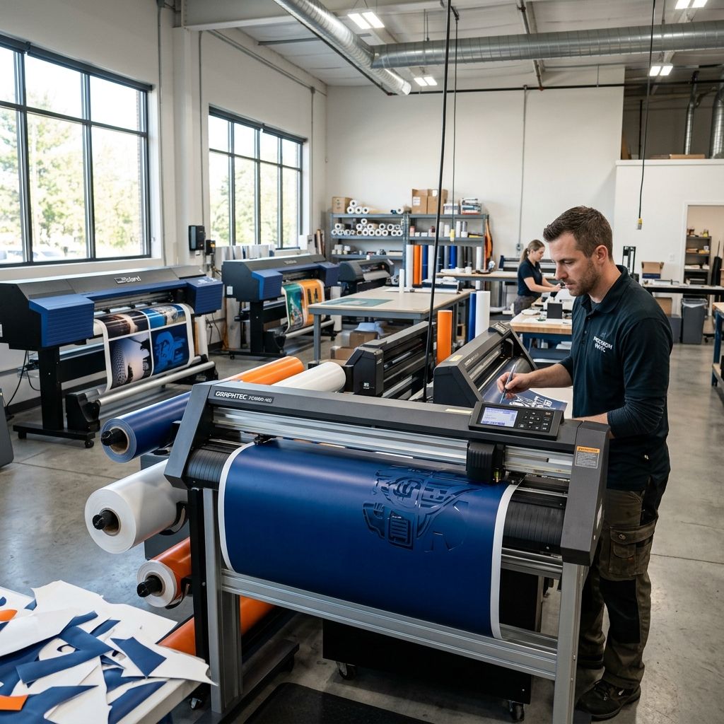
Choosing Between Cricut Maker 3 and Maker 4 Architecture
A shop-floor dissection of cutting force, feed roller mechanics, closed-loop gantry limits, and the real production economics of desktop digital die cutters.
Architectural Positioning & Bench Reality
Desktop digital cutters live in an awkward purgatory between craft hobby tables and industrial roll-fed plotters like Graphtec or Summa. The Cricut Maker 3 and the anticipated hardware revisions of the Maker series target small fabrication studios needing intermittent cutting, scoring, and rotary slicing across polymers, textiles, and chipboard. While marketing brochures push effortless creation and smart material speeds, shop reality reveals strict mechanical trade-offs: planetary gear backlash, proprietary cloud tethering, rubber roller degradation under heavy grit, and pinch-roller drift on runs exceeding two meters. Evaluate your unit cost and cycle amortization with our Cost Calculator before committing a production cell to this hardware class.
Gantry Construction and Linear Motion Limits
Under the glossy injection-molded ABS shell, the Maker chassis relies on an extruded aluminum transverse rail paired with stamped sheet-metal side plates. The tool carriage rides along a central polished steel shaft driven by a steel-reinforced polyurethane GT2 timing belt. Unlike industrial flatbed cutters running recirculating ball linear guide rails or twin-motor rack-and-pinion gantries, the Maker series relies on sintered bronze sleeve bushings or compact acetal polymer rollers pre-loaded against the guide rail.
This mechanical setup keeps mass minimal, but introducing transverse tool drag exposes structural compliance. When plunging a knife tool into 2.4 mm dense balsa or heavy matboard, normal downward force reaches up to 4000 grams-force (roughly 39.2 Newtons). Under that vertical load, the unsupported span of the guide shaft experiences measurable elastic deflection. In our workshop dial-indicator tests across a 330 mm span, downward blade force induces between 0.12 mm and 0.28 mm of shaft bowing at mid-stroke. On soft vinyl films, this deflection is negligible because knife downforce rarely exceeds 180 gf. However, on multi-pass structural materials, center cuts consistently exhibit shallower groove depths than cuts executed within 50 mm of the rigid stamped-steel side frames.
The drive train utilizes small-frame NEMA-style hybrid stepping motors driven by microstepping motor drivers. Position tracking remains predominantly open-loop. While optical home flag sensors establish zero indexing on startup, the machine has no secondary linear encoders along the Y-axis feed bed or X-axis crosshead. If a thick piece of acrylic or dense leather stalls the carriage knife during a high-speed transverse stroke, the controller drops step pulses without trigger shutdown, ruining the material blank and misaligning subsequent passes until full power-cycle re-homing.
Tool Head Carriage and the Adaptive Tool Gear System
The defining technical feature of the Maker architecture is its dual-carriage tool system. Carriage A accommodates passive trailing drag-knives, scoring pens, and stylus markers clamped via a quick-release lever latch. Carriage B contains an active brass spur-gear drive mechanism powered by an internal auxiliary motor inside the carriage block. This drive interfaces directly with the Maker Adaptive Tool System, turning rotary blades, knife drive shafts, debossing balls, and heavy scoring wheels.
The active gear interface allows the controller to adjust blade orientation mechanically rather than relying solely on material drag to cast the knife tip. For fabricators cutting fibrous textiles or composite aramid sheets, active blade steering prevents blade corner tearing. However, the brass drive pinion on the carriage and the mating acetal bevel gears inside the swappable tool cartridges introduce mechanical backlash. After approximately 80 to 120 operational hours cutting abrasive materials, gear tooth backlash increases from a baseline of 0.04 mm up to 0.18 mm. This play translates directly into incomplete closed loops at acute vector corners, where the tool leaves tiny micro-tabs uncut at path junctions.
- Downforce Capacity: 4000 gf (39.2 N) maximum active downforce on Tool Carriage B; 350 gf maximum passive drag force on Tool Carriage A.
- Gantry Drive Pitch: 2 mm pitch GT2 timing belt coupled to a 16-tooth drive pulley, providing roughly 32 mm linear travel per full motor revolution.
- Feed Roller Contact Pressure: Dual steel knurled drive shafts with vulcanized rubber secondary pinch rings delivering 14.5 N spring pre-load per roller contact point.
- Positional Repeatability: ±0.05 mm across X-axis over 250 mm span; ±0.45 mm cumulative drift over 3000 mm continuous Y-axis Smart Material feed without mat support.
- Vector Processing Ceiling: On-board firmware buffer limited to simplified SVG/DXF polyline conversions; stalls on spline nodes exceeding 4,000 vertices per layer.
Feed Roller Mechanics and Tracking Physics
Industrial vinyl plotters from manufacturers like Roland or Summa rely on grit-blasted steel drive drums paired with heavy-duty adjustable pinch wheels that seat into micro-grooves. In contrast, the Maker 3 architecture uses a continuous hexagonal drive axle carrying two molded rubber drive rollers and adjustable plastic margin guides. The machine feeds materials in two distinct modes: adhered to a reusable adhesive plastic carrier mat, or via stiffened backing liner known as Smart Materials.
The physics of friction between the knurled drive shaft, the carrier film, and the pinch roller determine tracking accuracy. In a production workshop, drift on the Y-axis is the primary killer of long cut jobs. Let us analyze the physical mechanics governing sheet traction under load.
Shear Force and Roller Friction Physics
When cutting dense rigid sheet stock or pulling rolls without a stabilizing carrier mat, the machine must overcome both inertial acceleration forces and knife drag friction without the rubber pinch wheels slipping across the plastic backing liner. The normal clamping force exerted by the tension spring on each pinch roller assembly is calibrated at approximately $F_N = 14.5\text{ N}$. With two contact rollers engaged, total clamping normal force is $29\text{ N}$.
The maximum static tractive force available before slip occurs along the feed direction is governed by Coulomb friction:
$$F_{tractive} = \mu_s \times (2 \times F_N)$$
For clean vulcanized rubber resting against smooth siliconized polyethylene terephthalate (PET) backing liner, the static friction coefficient is roughly $\mu_s \approx 0.42$. This yields a maximum tractive capacity:
$$F_{tractive} = 0.42 \times 29\text{ N} = 12.18\text{ N}$$
Now consider the drag resistance generated during a heavy cutting pass on 1.5 mm basswood or 2.0 mm chipboard using the drive knife. The cutting force is a compound vector of blade penetration resistance, material shear yield, and knife side-wall sliding friction:
$$F_{drag} = (k_s \times t \times w) + (F_{blade\_down} \times \mu_{blade})$$
Where $k_s$ is the specific cutting resistance of the material (for compressed dense matboard, $k_s \approx 18\text{ N/mm}^2$), $t$ is depth of cut per pass ($0.25\text{ mm}$), and $w$ is the effective blade bevel kerf width ($0.4\text{ mm}$):
$$F_{shear} = 18\text{ N/mm}^2 \times 0.25\text{ mm} \times 0.4\text{ mm} = 1.80\text{ N}$$
Adding the lateral sliding friction of the knife shaft against the kerf wall under 35 N downward preload ($\\mu_{blade} \approx 0.15$):
$$F_{friction} = 35\text{ N} \times 0.15 = 5.25\text{ N}$$
Total resistance along the cut vector reaches $F_{drag} = 1.80 + 5.25 = 7.05\text{ N}$. If the tool executes an oblique cut at 45 degrees, the lateral vector component acting against the Y-axis feed rollers is:
$$F_{Y\_load} = F_{drag} \times \sin(45^\circ) + m_{sheet} \times a_{feed}$$
With high-speed directional reversals where acceleration $a_{feed} = 1.5\text{ m/s}^2$ on a 400 g workpiece carrier, the dynamic peak force climbs to $7.05 \times 0.707 + (0.4 \times 1.5) = 4.98 + 0.60 = 5.58\text{ N}$. This represents over 45% of the total tractive slip limit ($12.18\text{ N}$). If grease, fine paper dust, or adhesive bleed from an aged cutting mat contaminates the roller surface, the friction coefficient $\mu_s$ plummets below 0.22, collapsing tractive force to $6.38\text{ N}$. Under these conditions, the rollers instantly slip during acceleration spikes, resulting in a skewed cut pattern and irrecoverable step loss.
Industrial Specifications & Architecture Comparison
When selecting between the Maker 3 chassis and evaluating whether to upgrade or standardize your workshop on revised Maker generation units, examining raw mechanical capabilities clarifies where the limits reside:
| Engineering Parameter | Cricut Maker 3 Architecture | Workshop Heavy-Duty Standard | Failure / Wear Mode |
|---|---|---|---|
| Downforce System | Solenoid & Cam Gear (Max 4000 gf) | Voice-coil actuator (500-1000 gf) | Gear tooth rounding; motor thermal drift |
| Y-Axis Tracking | Dual rubber pinch rollers on hex shaft | Segmented micro-grit grit rollers | Skew on cuts exceeding 1.8 meters |
| Guide Rails | Single polished 12 mm steel bar + bushing | Twin linear ball guides (MGN9 / MGN12) | Center deflection under high plunge force |
| Cut Speed (Smart Mats) | Up to 203 mm/s (8 in/s) straight line | Up to 1000 mm/s vector traversal | Vibration ripple on fine text below 6 pt |
| Motor Feedback | Open-loop hybrid microsteppers | Closed-loop digital DC servomotors | Loss of sync during blade material jams |
| Software Interface | Proprietary cloud (Design Space) | Direct HP-GL, G-code, or local RIP | Stalls on offline networks; path distortion |
| Tool Mount Mechanism | Plastic lever clamp collar | Billet aluminum clamping collar | Collar flex under multi-axis lateral drag |
Software Ecosystem Tethering vs Shop Autonomy
Any veteran shop technician knows that machine mechanics only account for half the asset value; software control determines uptime. The Maker ecosystem enforces an unyielding umbilical cord to Cricut Design Space. Unlike commercial plotters that accept standard HP-GL commands over a raw serial port, or CNC routing cutters parsing standard G-code, the Maker requires communication through Cricut's cloud servers or encrypted desktop application.
For high-throughput makers, this introduces severe friction points. First, complex vector files containing thousands of spline nodes—such as intricate gaskets, dense heat transfer vinyl micro-patterns, or architectural fretwork—frequently choke the vector pre-processor. The software attempts to simplify bezier curves in ways that degrade precision tolerances. Similar to challenges encountered when Deploying 3D Printing Tool Sets in Commercial Farms, relying on closed tool chains introduces single-point operational vulnerabilities.
Second, working in secure fabrication spaces without high-speed internet access creates critical downtime. If the proprietary server experiences an outage or requires mandatory firmware upgrades prior to cutting, your physical machine is dead in the water. For an operation billing hourly shop rates, a cloud lockout costs real money.
Tool Head Maintenance and Wear Point Lifecycle
To keep the Maker running with tight repeatability, technicians must implement a strict hardware maintenance regimen. These machines lack automatic oiling ports or sealed bearing blocks, meaning workshop dust quickly turns factory grease into an abrasive grinding paste.
The primary wear points require inspection on a weekly or 50-operating-hour cycle:
- Drive Roller Decontamination: Wipe down rubber feed wheels with 99% isopropyl alcohol using lint-free swabs. Never use acetone or chlorinated solvents, which embrittle vulcanized nitrile rubber.
- Brass Pinion Lubrication: Apply a dry PTFE micro-lubricant spray to Carriage B's brass drive gear. Never use wet lithium grease or mineral oil; wet lubricants capture paper dust and vinyl shavings, packing the gear teeth and causing severe pitch binding.
- Shaft Polishing & Bushing Clean: Inspect the primary 12 mm horizontal steel rail for particulate buildup. Clean with a light wipe of ISO VG 32 synthetic machine oil, cycling the carriage manually while powered off to push debris out of the bronze sleeve bushings.
- Blade Bearing Purge: Remove the rotary blade or deep-point blade from its aluminum housing. Blow compressed dry air through the bearing race to clear micro-fibers, which otherwise lock the internal miniature radial ball bearings and turn rolling drag blades into fixed scrapers.
When peeling finished parts from adhesive mats, avoid using broad shop scrapers that gouge the adhesive substrate. Using specialized tools such as the spatulas evaluated in our BuildTak Spatula Tool Review: Pros, Cons & Field Reality preserves the delicate acrylic adhesive coat without leaving residual ridges that interfere with sheet feed calibration.
Thermal Drift and Duty Cycle Realities
The Maker series is engineered for intermittent consumer cycles rather than continuous eight-hour shop shifts. In continuous cutting trials inside a 22°C ambient shop, the carriage drive motor and the tool B auxiliary rotary motor reach casing temperatures of 58°C within two hours of heavy cutting. Because the plastic carriage enclosure has no active brushless fan cooling or aluminum heatsink finning, heat conducts directly into the carriage chassis.
As the carriage warms, thermal expansion in the plastic structural collars holding Carriage B causes the brass drive gear mesh to tighten slightly. Technicians will notice this as an audible acoustic change—a higher-pitched gear whine during direction changes—accompanied by an increase in current draw from the main power board. If operating in warm environments without air conditioning, run the machine on a maximum 45-minute cutting cycle followed by a 15-minute cool-down rest to prevent stepper motor coil degradation.
Frequently Asked Questions
Can the Cricut Maker cut genuine 3 mm sheet acrylic reliably?
No, the machine lacks the downward force and spindle power to mill through 3 mm cast acrylic, only scoring the surface shallowly before blade deflection causes wandering. For sheets thicker than 1.5 mm, score-and-snap or dedicated laser cutting is required.
Why does long vinyl drift out of alignment when using Smart Materials without a cutting mat?
Pinch rollers lack independent micro-grit tracking drums, so minor manufacturing variations in roller diameter cause the material to skew over feed lengths exceeding two meters.
How often should the Adaptive Tool System brass gear be replaced or serviced?
Clean and re-lubricate the gear with dry PTFE every 50 hours of rotary or knife tool use; replace individual tool cartridges if rotational play exceeds 0.2 mm.
Can you drive the Cricut Maker directly with Inkscape or Adobe Illustrator via standard plugins?
No, the machine controller firmware requires encrypted data packets that can only be generated through the official Cricut Design Space software pipeline.
Related Intel
xTool M1 Ultra Buying Guide: Shop Floor Reality
An engineering evaluation of the xTool M1 Ultra 4-in-1 machine, assessing diode laser optics, drag-knife tolerances, inkjet reliability, and real workshop payback.
Silhouette Portrait 4 for Small-Batch Production
With proper belt tension and blade depth calibration, the Silhouette Portrait 4 achieves <1% reject rates for small-batch cutting of labels and thin materials. Replace roller O-rings every 500 feet to maintain Y-axis registration. A loose Y-belt causes banding; tighten until faint twang, then back off quarter-turn.
Fixing StarCraft SOLO Error E-04 Spindle Overload
Error E-04 on the StarCraft SOLO CNC is usually a mechanical bind, not a true overload. This guide covers real diagnostics: collet alignment, bearing inspection, and VFD current readings to get you back to cutting.