Full Spectrum Laser Muse Titan Material Settings Guide

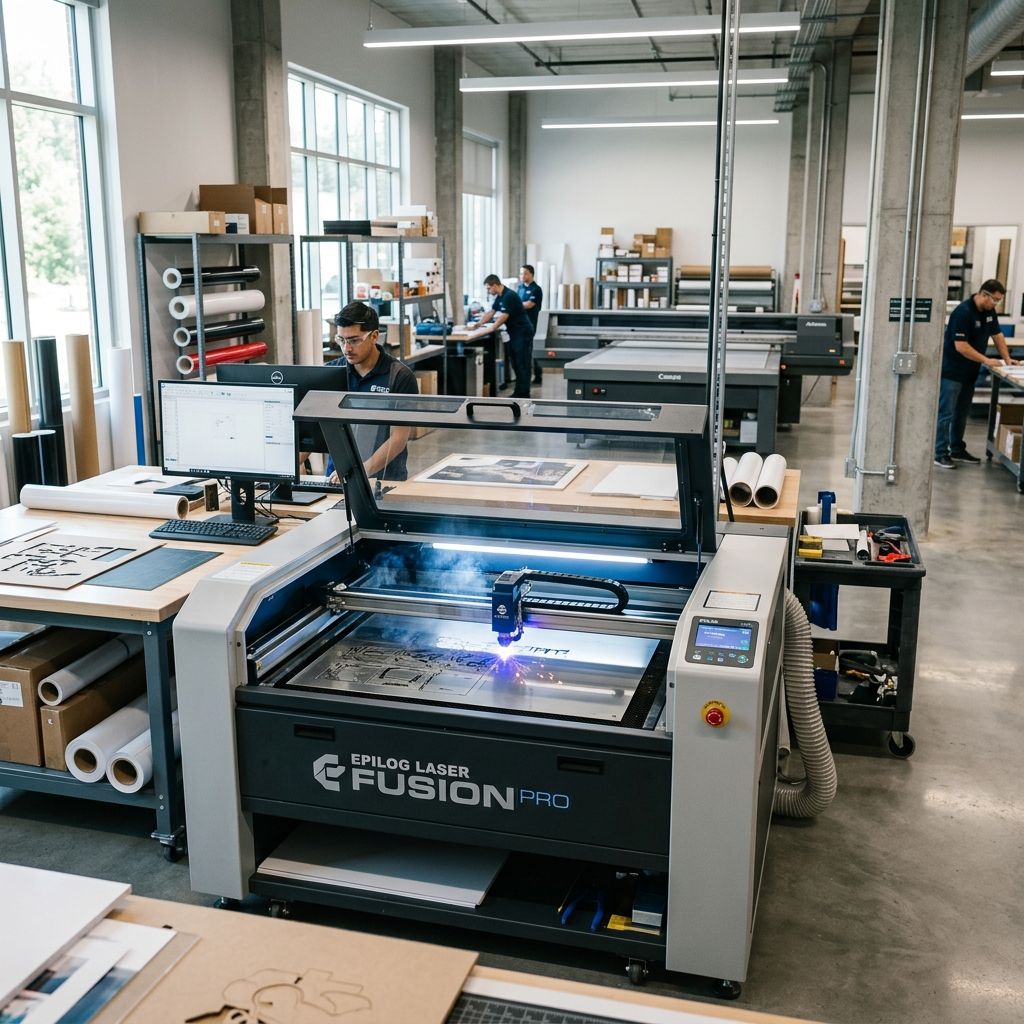
Full Spectrum Laser Muse Titan: Material Settings and Beam Physics
An empirical machining handbook for CO2 laser cutting, covering 10.6 μm photothermal absorption, kerf geometry, and material feed optimization.
Optical Architecture & Infrared Photon Kinetics
The Full Spectrum Laser Muse Titan deploys a sealed, water-cooled CO2 laser tube emitting a Gaussian TEM00 beam in the far-infrared spectrum at a 10.6 μm wavelength. At this wavelength, non-metallic organic polymers (such as cast polymethyl methacrylate and polyoxymethylene) and lignocellulosic woods exhibit resonant vibrational absorption bands within their covalent backbone bonds. This immediate optical coupling yields localized photothermal sublimation and depolymerization rather than mechanical ablation, provided beam focus, assist air pressure, and vector speed are properly synchronized inside RetinaEngrave.
Far-Infrared Absorption Mechanics Across Substrates
Selecting material settings on an industrial 75W to 100W CO2 gantry is fundamentally an exercise in balancing laser energy flux against the thermal diffusivity of the target stock. Unlike visible or near-infrared fiber lasers (1.06 μm) and visible diode lasers that reflect heavily off clear plastics as seen in diode systems like the Gluwphy Diode Laser Engraver Material Guide, 10.6 μm infrared radiation is completely opaque to standard transparent optical glasses and clear acrylics.
When the 10.6 μm photon beam strikes cast PMMA (acrylic), photon energy is absorbed within the initial 20 to 40 micrometers of the substrate. This intense photon density triggers thermal unzipping depolymerization, converting solid polymer chains directly back into gaseous methyl methacrylate monomer without passing through a prolonged liquid phase. The escaping gas leaves behind a pristine, flame-polished edge. In contrast, extruded acrylic possesses lower molecular weight and broad polymer chain dispersity, leading to molten boiling, bubbling, and heavy edge burring unless traverse speeds are drastically increased.
Optical Gantry and Auxiliary Pneumatic Parameters
Process repeatability on the Muse Titan relies on rigid kinematic delivery and strict environmental conditioning across the 48 by 24 inch bed.
- Wavelength & Spatial Beam Mode: 10.6 μm far-infrared; TEM00 spatial mode (M² beam propagation parameter < 1.2).
- Standard Focusing Optic: 2.0-inch (50.8 mm) focal length Zinc Selenide (ZnSe) meniscus lens with anti-reflective coating.
- Air Assist Pneumatic Range: 15 to 45 PSI oil-free dry compressed air delivered coaxial to the beam nozzle.
- Chiller Operating Envelope: Continuous closed-loop chilled distilled water maintained strictly between 18°C and 21°C.
- Exhaust Evacuation Flow Rate: Minimum 450 CFM inline blower extraction across downdraft honeycomb table.
- RetinaEngrave Pulse Density: Adjustable from 250 to 1,000 Pulses Per Inch (PPI) for vector cutting and raster engraving.
Laser Beam Spot Dynamics and Energy Fluence Calculation
To establish rigorous material settings rather than relying on rough dial guessing, technicians must calculate focal spot diameter, depth of focus (Rayleigh length), and surface energy fluence.
The diffraction-limited focused beam spot diameter (d_{spot}) produced by a ZnSe lens is governed by lens focal length, laser wavelength, and raw beam diameter entering the optic:
d_{spot} = \frac{4 \cdot \lambda \cdot f}{\pi \cdot D_{beam}}
Where \lambda is the laser wavelength (10.6 × 10^{-3} mm), f is the focal length (50.8 mm for a standard 2.0-inch lens), and D_{beam} is the collimated raw beam diameter exiting the beam expander and final turning mirror (nominal 8.0 mm).
Calculating the focused spot diameter:
d_{spot} = \frac{4 \cdot (0.0106 \text{ mm}) \cdot (50.8 \text{ mm})}{3.14159 \cdot (8.0 \text{ mm})} = \frac{2.1539}{25.1327} = 0.0857 \text{ mm} \approx 85.7 \,\mu\text{m}
The depth of focus or Rayleigh range (z_R), over which the beam waist cross-sectional area doubles, determines the maximum stock thickness that can be cut with parallel vertical walls:
z_R = \frac{\pi \cdot (d_{spot} / 2)^2}{\lambda} = \frac{3.14159 \cdot (0.04285 \text{ mm})^2}{0.0106 \text{ mm}} = \frac{0.005769}{0.0106} = 0.544 \text{ mm}
Because the effective Rayleigh depth is approximately 1.09 mm total confocal parameter, cutting stock thicker than 3 mm requires deliberate focal point placement below the top surface (typically one-third into the material thickness) to balance kerf divergence between the upper and lower faces.
Workshop Practical Calculation: Energy Fluence & Depolymerization of 6 mm Cast Acrylic
Consider an industrial workshop profiling 6.0 mm thick cast PMMA sheet components designed in CAD suites like those discussed in Three OpenSCAD Problems and How to Solve Them. The Muse Titan operates an 85W CO2 tube calibrated at 85% commanded power (actual delivered optical power P = 72.25 W). The vector feed velocity is set to v = 12.0 mm/s.
We first calculate the Linear Energy Density (E_L), which represents the optical energy delivered per millimeter of cutting path:
E_L = \frac{P}{v} = \frac{72.25 \text{ W}}{12.0 \text{ mm/s}} = 6.021 \text{ J/mm} \text{ (or } 6,021 \text{ J/m)}
Next, we determine the Surface Energy Fluence (F), representing optical energy delivered per unit area of the focused beam spot:
F = \frac{P}{v \cdot d_{spot}} = \frac{72.25 \text{ W}}{(12.0 \text{ mm/s}) \cdot (0.0857 \text{ mm})} = \frac{72.25}{1.0284} = 70.25 \text{ J/mm}^2 = 7,025 \text{ J/cm}^2
Thermodynamic Mass Sublimation Balance
The average kerf width measured across the 6.0 mm cut is approximately 0.16 mm (1.6 × 10^{-4} m). The volume of acrylic material vaporized per second is:
\dot{V} = \text{kerf} \cdot \text{thickness} \cdot v = (0.16 \text{ mm}) \cdot (6.0 \text{ mm}) \cdot (12.0 \text{ mm/s}) = 11.52 \text{ mm}^3\text{/s} = 1.152 \times 10^{-2} \text{ cm}^3\text{/s}
Given cast PMMA density \rho = 1.18 \text{ g/cm}^3, the mass removal rate (\dot{m}) is:
\dot{m} = 1.152 \times 10^{-2} \text{ cm}^3\text{/s} \times 1.18 \text{ g/cm}^3 = 0.01359 \text{ g/s}
Depolymerization of PMMA requires sensible heating from 20°C to the thermal unzipping ceiling temperature of 380°C (c_p ≈ 1.46 J/g·K) plus the latent endothermic heat of depolymerization (\Delta H_{depol} ≈ 870 J/g):
Q_{req} = \dot{m} \cdot [c_p \cdot \Delta T + \Delta H_{depol}] = 0.01359 \cdot [(1.46 \cdot 360) + 870] = 0.01359 \cdot [525.6 + 870] = 18.97 \text{ W}
The theoretical power required to vaporize the trench is 18.97 Watts. With 72.25 Watts delivered, the excess optical energy (53.28 W) compensates for conductive heat loss into the adjacent acrylic bulk (creating the fire-polished smooth edge), Fresnel surface reflection at the entering cut front, and transmission through the kerf slot. If the velocity is slowed to 6 mm/s, excess energy density climbs to 12.0 J/mm, causing excessive heat-affected zone expansion, severe kerf widening, and localized flaming.
Production Material Compatibility & Calibration Matrix
Material settings require fine adjustments depending on stock grade, moisture content, and optical density. The matrix below details empirical baseline parameters for an 85W Muse Titan equipped with a 2.0-inch ZnSe lens.
| Material & Grade | Nominal Thickness | Power (%) | Velocity (mm/s) | Air Assist (PSI) | Focal Offset | Edge Finish Quality & Kerf Taper |
|---|---|---|---|---|---|---|
| Cast Acrylic (PMMA - GS) | 3.0 mm (1/8 in) | 65% | 22.0 | 12 - 15 | On Surface (0.0 mm) | Pristine flame-polished edge; kerf taper < 0.8° |
| Cast Acrylic (PMMA - GS) | 6.0 mm (1/4 in) | 85% | 12.0 | 15 - 18 | -2.0 mm (Into stock) | Optically clear vertical face; kerf width 0.16 mm |
| Extruded Acrylic (PMMA - XT) | 3.0 mm (1/8 in) | 55% | 25.0 | 25 - 30 | On Surface (0.0 mm) | Slight edge lip; prone to stress crazing under alcohol |
| Baltic Birch Plywood (BB/BB) | 3.0 mm (1/8 in) | 70% | 20.0 | 35 - 40 | On Surface (0.0 mm) | Golden brown edge; clean cut through interior urea glue |
| Baltic Birch Plywood (Exterior) | 6.0 mm (1/4 in) | 95% | 8.0 | 40 - 45 | -2.0 mm (Into stock) | Dark charring; phenolic exterior glue slows penetration |
| Delrin / Acetal Homopolymer (POM-H) | 3.0 mm (1/8 in) | 80% | 18.0 | 30 - 35 | On Surface (0.0 mm) | Ultra-clean square edge; zero char; formaldehyde fumes |
| MDF / High Density Fiberboard | 4.5 mm (3/16 in) | 85% | 10.0 | 35 - 40 | -1.5 mm (Into stock) | Heavy dark soot; resin vaporizes slowly; high air assist |
| Vegetable Tanned Leather (Cowhide) | 2.5 mm (6 oz) | 45% | 28.0 | 20 - 25 | On Surface (0.0 mm) | Clean cut with minimal edge soot; heavy organic odor |
RetinaEngrave Pulse Tuning and Vector Optimization
RetinaEngrave provides granular control over vector firing modes, specifically continuous wave (CW) versus pulsed PPI (pulses per inch). For thin organic materials prone to scorching, such as delicate woods and paperboards, continuous wave firing floods the kerf boundary with persistent conductive heat, creating excessive soot halos.
By switching to PPI mode and setting pulse density between 300 and 500 PPI, the laser tube fires discrete, high-peak-power pulses synchronized to gantry encoder ticks. Each pulse vaporizes a micro-hole while the brief inter-pulse dwell allows air assist gas to quench the kerf edge before lateral heat conduction can ignite adjacent cellulose fibers. For thick cast acrylic, however, continuous wave mode remains mandatory; pulsing creates micro-striations and scallops along the cut edge, destroying optical clarity.
Pneumatics, Optics Maintenance, and Alignment Diagnostics
A CO2 laser cutter cannot maintain calibrated material cut tables if optical power degrades along the beam delivery path. Technicians must conduct rigorous maintenance audits every 40 laser operating hours:
- ZnSe Focal Lens Inspection: Remove the nozzle cone and inspect the 2.0-inch meniscus lens under oblique lighting. Condensation, smoke residues, or spattered wood pitch create localized absorption hotspots. Because ZnSe has low thermal shock tolerance, an uncleaned optic will crack within minutes of 80W power firing. Clean exclusively with spectrophotometric-grade acetone or electronic IPA using optical lens tissue in a single drop-and-drag motion.
- Beam Alignment Target Test: Apply thermal paper or blue painter tape over Mirror 3 entrance aperture at all four bed corners (top-left, top-right, bottom-left, bottom-right). Fire a 20 ms test pulse at 15% power. The burn spot must remain concentric within a 1.0 mm tolerance ring across the entire 48-inch travel. Beam walk indicates gantry rail misalignment or loose mirror locknuts.
- Air Assist Desiccant Drain: Water droplet contamination inside the air assist line will instantly pit the ZnSe lens when impacted by 10.6 μm radiation. Drain inline pneumatic desiccant traps daily.
- Coolant Conductivity & Temperature Drift: Check the CW-5200 chiller daily. If coolant temperature drifts above 22°C, CO2 gas excitation efficiency declines rapidly, reducing actual output beam power by up to 1.5% per degree Celsius above setpoint.
Forbidden Workshop Materials and Pyrolysis Hazards
Several commercial polymers look identical to safe plastics but produce deadly halogen gas or corrosive acids when exposed to CO2 laser beams. Technicians must maintain strict stock verification protocols:
- Polyvinyl Chloride (PVC / Vinyl): Strictly banned. Thermal cutting of PVC liberates gaseous hydrogen chloride (HCl). When HCl contacts ambient air humidity, it synthesizes hydrochloric acid, destroying linear steel guide rails, corroding stepper motor bearings, and producing lethal pulmonary toxins.
- Polytetrafluoroethylene (PTFE / Teflon): Emits highly toxic fluoropolymer fumes and perfluoroisobutylene gas that cause polymer fume fever upon inhalation.
- Polycarbonate (PC / Lexan): Absorbs 10.6 μm radiation poorly; rather than clean sublimation, polycarbonate chars into black sticky soot, bursts into flames, and produces structurally damaged yellow cut faces.
- Carbon Fiber Prepregs: The epoxy binder evaporates while conductive carbon fibers fray and blow into gantry electrical rails, triggering short circuits in motor drive stages.
Frequently Asked Questions
Why does 6 mm acrylic cut with an angled or beveled taper instead of a vertical 90-degree edge?
Laser beams converge to a waist and diverge outward. To minimize edge taper across 6 mm stock, lower the focal height by 2.0 mm beneath the surface to place the narrowest beam waist inside the mid-plane of the sheet.
Can the Muse Titan cut sheet metals like stainless steel or aluminum?
No. Standard 10.6 μm CO2 lasers at 85W to 100W power levels reflect more than 98% of incident optical energy off bare reflective metal surfaces. Cutting 1 mm mild steel requires oxygen-assisted fiber lasers or specialized 150W+ pulsed CO2 sources with capacitive auto-height heads.
What causes heavy white flashback marks on the underside of cut acrylic?
Flashback occurs when the laser beam penetrates the stock and reflects off standard aluminum honeycomb grid ribs. Elevate the acrylic sheet on pointed brass pin supports or sacrifice a scrap cardboard layer to prevent reflective energy from scarring the bottom face.
How can burning and charring be eliminated when cutting Baltic birch plywood?
Increase air assist pressure to 35-40 PSI, increase vector speed while using multiple high-speed passes if necessary, and mask the top and bottom faces of the wood sheet with wide paper transfer tape prior to cutting.
Critical Life-Safety and Optics Protocol
Never leave the laser cutter unattended during vector cutting operations. Lignocellulosic woods and acrylic vapors present acute fire risks if assist air drops below 15 PSI or gantry movement stalls under active beam fire. Always verify that closed-loop water chiller flow sensors and exhaust interlocks are operational prior to initiating production cutting runs.
Related Intel
xTool S1 20W & 40W Workshop Production and ROI Guide
Turn the enclosed xTool S1 diode laser into an autonomous production cell with optical density math, custom nesting jigs, and high-velocity air assist tuning.
xTool P2S 55W CO2 Laser Review: Pros, Cons, and Specs
xTool P2S 55W CO2 laser: industrial accuracy (±0.05 mm) with 55W beam, but requires exhaust and air assist upgrades for continuous use. No native LightBurn support. Best for small-batch manufacturing where cost and precision matter.
ROI of the Thunder Laser Nova 24/35
We installed three Thunder Laser Nova machines in small shops. This article covers measured ROI, hardware requirements, and first-week workflow to turn a laser cutter into a profit center.