RepRapFirmware Pros and Cons: Industrial Motion Guide


RepRapFirmware: Shop-Floor Evaluation for Industrial Automation and Multi-Tool Rigs
An unfiltered engineering breakdown of Duet3D's motion engine: where standalone macro execution beats host-based architectures, and where high board costs bite back.
Executive Architectural Verdict
RepRapFirmware (RRF) occupies a specialized niche in high-reliability additive manufacturing, tool-changing gantries, and custom multi-axis CNC machines. Running bare-metal on 32-bit ARM Cortex-M4/M7 processors (Duet 2 and Duet 3 series), it bypasses the OS overhead of Linux-dependent engines like Klipper while completely eliminating the recompile-and-flash cycle required by Marlin. Configuration resides in human-readable G-code macros (config.g) interpreted dynamically at boot or on-the-fly. For automated production cells demanding deterministic hardware interrupts, native CAN-FD distributed toolheads, and integrated web telemetry without an external single-board computer, RRF remains the industrial benchmark. However, higher per-axis driver costs and a steeper macro programming curve make it overkill for standard single-nozzle Cartesian workhorses. Calculate machine throughput limits beforehand using our Print Speed Calculator to verify if your mechanics warrant high-bandwidth closed-loop control.
Architecture and Execution Model: Standalone Embedded vs Host-Client Rigs
When running a fleet of production printers or specialized deposit heads in a fabrication shop, the underlying motion architecture dictates long-term maintenance overhead. The modern additive industry has largely fractured into three distinct camps: monolithic recompiled firmware (Marlin), host-client distributed systems running Python on a Raspberry Pi (Klipper), and distributed real-time embedded firmware (RepRapFirmware). Understanding this division separates functional manufacturing from perpetual bench troubleshooting.
Marlin forces the technician to recompile an entire C++ binary in PlatformIO or Arduino IDE every time a thermistor table changes, a probe offset drifts, or an endstop pin is reassigned. In a prototype workshop where tooling configurations evolve weekly, this recompile cycle creates friction and versioning debt across machine clusters. Klipper resolves this configuration bottleneck by offloading kinematics and planning to an asynchronous Linux host, pushing pre-computed step pulses down a USB pipe to bare microcontrollers. While flexible, Klipper introduces several points of failure: micro-SD card wear on the single-board computer, Linux kernel scheduler hiccups during heavy background network activity, and severed USB serial handshakes mid-cycle that abort multi-hour builds.
RepRapFirmware handles motion deterministically on the silicon itself. The ATSAM4E8E (Duet 2) or ATSAME54 (Duet 3 6HC) microcontrollers manage path planning, kinematics, step generation, thermal PID loops, and Ethernet or Wi-Fi web serving concurrently through lightweight real-time operating system tasks. Everything—from stepper current and microstepping to cinematic input shaping and complex kinematics—is configured through plain text files stored on an onboard FAT32 SD card. Modifying mechanical geometry requires nothing more than editing a line in config.g via the Duet Web Control browser interface and executing an M999 software restart or applying the command live in the console.
Field Strengths: Where RepRapFirmware Wins on the Shop Floor
- Live Macro Execution: Every configuration parameter, kinematic adjustment, and calibration routine is an executable G-code macro with native conditional branching (if, while, var), allowing intricate physical sequences without compiling custom firmware builds.
- Deterministic Bare-Metal Timing: Real-time task scheduling eliminates operating system jitter, dropped serial packets, and USB driver timeouts common in host-dependent architectures during high-velocity moves.
- CAN-FD Distributed Toolheads: The Duet 3 ecosystem connects toolboards, closed-loop stepper expansion boards, and sensor breakouts across an industrial differential CAN-FD bus running at 1 Mbps with CRC verification, cutting wiring looms to four conductors.
- Native Object Model and Telemetry: Every state variable—stepper temperatures, stall-guard counters, motor phase resistance, heatsink thermistors—is continuously exposed through a structured JSON hierarchy via HTTP, WebSocket, or MQTT.
- On-the-Fly Kinematic Remapping: Supports complex Cartesian, CoreXY, CoreXYU, Polar, Scara, and Rotary Delta setups with dynamic toolhead coordinate offsets essential for multi-gantry and tool-changing mechanisms.
The operational advantage of RRF is its conditional macro engine. In automated tool-changing rigs such as the E3D ToolChanger or custom Jubilee frames, picking and docking a toolhead requires sensing docking pin engagement, reading carriage limit switches, modifying nozzle coordinate offsets, restoring pressure advance parameters, and executing wipe trajectories. In Marlin, this requires hard-coded custom C routines that are painful to modify. In Klipper, it requires nested Jinja2 templates that become cumbersome to debug. In RRF, you write native G-code files like tpre0.g, tpost0.g, and tfree0.g. You query internal variables directly: if the nozzle temperature is below extrusion threshold, the firmware pauses the pickup, warms the heater block, verifies thermal stability, and resumes the wipe routine without external host intervention.
Shop-Floor Tradeoffs and Mechanical Drawbacks
- Significant Upfront Hardware Investment: Duet 3 mainboards and genuine expansion boards command industrial pricing ($180 to $350+) compared to budget 32-bit maker boards running open-source chips.
- Stricter CAN-FD Bus Termination: Distributed nodes require rigorous 120-ohm bus termination resistors, clean twisted-pair cabling, and proper shielding to prevent frame ground loops in noisy factory environments.
- Steeper Macro Debugging Curve: Writing complex macros with state variables, nested loops, and global arrays requires understanding firmware state machines; a typo in a tool change script can crash a carriage into an aluminum bed mount.
- Smaller Third-Party Desktop Ecosystem: While dominant in commercial rigs, fewer consumer desktop printers offer drop-in mount brackets or pre-built wiring adapters for Duet boards.
- Limited Automated Resonance Mapping: While RRF supports resonance compensation algorithms (MZV, ZVD, EI, DDA), gathering accelerometer sweeps historically required manual script processing or secondary boards compared to automated single-click plots on Linux hosts.
Budget constraints are the primary barrier to adoption. Outfitting an IDEX (Independent Dual Extruder) machine with a Duet 3 6HC and two Duet 3 1LC toolboards easily pushes electrical hardware costs past $450 before factoring in power supplies, fans, and wiring. On budget manufacturing machines, shop managers often hesitate when a generic control board paired with a cheap SBC costs a third of that. However, that calculation ignores labor hours: diagnosing intermittent USB disconnects or hunting down ground loops on budget electronics quickly eats through initial savings. In production settings where downtime costs hundreds of dollars per hour, the rock-solid reliability of an isolated industrial microcontroller pays for itself within weeks.
Technical Specification and Platform Benchmark
Below is a comparative breakdown of RepRapFirmware running on Duet 3 hardware against common industrial and prosumer motion architectures operating in production environments.
| Metric / Feature | RepRapFirmware v3.5 (Duet 3 6HC) | Klipper (Linux SBC + MCU) | Marlin v2.1 (Monolithic 32-Bit) |
|---|---|---|---|
| Processor Architecture | ATSAME54 32-bit ARM Cortex-M4F @ 120 MHz | Broadcom BCM2711 (Pi 4) + STM32F407 MCU | STM32F401 / STM32G0B1 @ 64-84 MHz |
| Configuration Protocol | Plain text G-code macros (config.g) on SD card | INI format text file (printer.cfg) on Linux host | C++ source headers recompiled to binary (.bin) |
| Motion Loop Determinism | Bare-metal RTOS with dedicated step-timer ISR | Microcontroller step buffer fed by host queue | Bare-metal monolithic interrupt service routine |
| Distributed Expansion Bus | CAN-FD (1 Mbps differential, hardware CRC) | USB / CAN via Linux socketcan | Limited SPI / UART chained driver boards |
| Max Step Generation Rate | Up to 2,000,000 steps/sec across channels | 600,000 - 1,200,000 steps/sec (microcontroller dependent) | 300,000 - 500,000 steps/sec (timing limits) |
| Tool-Changer Support | Native dynamic coordinate remapping & macro hooks | Supported via custom Python modules or Jinja macros | Hard-coded toolchange routines in firmware |
| Thermal Safety Architecture | Hardware watchdog + multi-stage software trip | Host watchdog + MCU disconnect protection | Integrated thermal runaway interrupt handler |
| Web Interface / Networking | Duet Web Control (DWC) hosted directly on board | Mainsail / Fluidd served by Linux Nginx instance | ESP3D module or external OctoPrint host |
Physics and Kinematic Calculation: Step Frequencies, Bus Latency, and Pulse Ceilings
In high-speed production gantries, motion firmware stability hinges on step interrupt timing and bus bandwidth. When driving high-lead ball screws or fine pitch timing belts paired with 0.9° stepper motors (400 full steps per revolution) interpolated to 256 microsteps via Trinamic TMC5160 drivers, the processor must generate high step pulse frequencies without accumulating interrupt jitter.
Consider an industrial CoreXY gantry running a target velocity of 400 mm/s. The gantry utilizes GT2 belts (2 mm tooth pitch) with 20-tooth pulleys, driven by 0.9° stepper motors configured for 1/16 physical microstepping with 1/256 interpolation:
1. Belt Pitch Diameter and Resolution:
Pitch Circumference = 20 teeth × 2.0 mm/tooth = 40 mm per motor shaft revolution.
Steps per Millimeter = (400 full steps/rev × 16 microsteps) / 40 mm = 160 steps/mm.
2. Step Frequency at Maximum Gantry Velocity:
When running a non-print traverse at 400 mm/s:
f_step = v × steps/mm = 400 mm/s × 160 steps/mm = 64,000 steps/sec per axis motor.
On a CoreXY kinematic system, pure diagonal moves force one motor to deliver the vector resultant of both axes, increasing peak motor velocity by a factor of the square root of 2:
f_peak = 64,000 × 1.4142 ≈ 90,510 Hz (90.51 kHz).
The ATSAME54 Cortex-M4F processor on the Duet 3 runs at 120 MHz with a dedicated hardware timer producing step pulses with a minimum pulse width of 1 microsecond. At 90.5 kHz, each step interval is 11.05 microseconds. The step ISR consumes roughly 45 clock cycles (0.375 microseconds) per interrupt. The CPU load dedicated strictly to step generation remains under 3.5%:
CPU_load = (0.375 μs / 11.05 μs) × 100 ≈ 3.39%.
3. Distributed Toolhead Bandwidth over CAN-FD:
When offloading extruder steppers, hotend thermistors, and part fans to a Duet 3 Toolboard 1LC, data flows over CAN-FD at 1 Mbps. A standard motion control synchronization packet contains 64 payload bytes plus arbitration, CRC, and framing bits (approximately 580 bit periods per transmission cycle).
Frame Transmission Time = 580 bits / 1,000,000 bps = 0.58 ms (580 microseconds).
At a motion update loop rate of 250 Hz (4 ms period), the bus utilization for a single toolboard is:
Bus_utilization = (0.58 ms / 4.0 ms) × 100 = 14.5%.
This leaves 85.5% of total bus capacity free for auxiliary sensor telemetry, closed-loop encoder feedbacks, and emergency halt frames. Because transmission is differential and hardware-arbitrated, packet collisions do not halt motion planning, maintaining deterministic trajectory execution even under heavy electrical noise from adjacent stepper coils.
Toolhead Mechanics and G-Code Macro Architecture
Where RepRapFirmware excels is in eliminating mechanical slop and calibration drift across complex assemblies. Consider a tool-changing production machine equipped with an inductive probe, an optical filament monitor, and multiple swappable toolheads. In standard setups, aligning lead screws and gantry parallelism requires tedious manual leveling. When paired with mechanical hardware like the THSL-300-8D Lead Screw Setup and Alignment Guide, RRF allows automated leadscrew desync correction using independent stepper drivers on each Z-axis motor.
In RRF, leveling multiple Z leadscrews is handled by the G32 macro calling bed.g. The firmware probes points directly above each physical screw, calculates the tilt plane using least-squares fitting, and commands each stepper driver to move the exact fraction of a degree needed to square the bed carriage against the gantry rails. No manual thumbwheel twisting, no mechanical binding, and no hunting for calibration shims. The machine self-trues before every batch cycle.
Thermal expansion of long aluminum printer beds introduces significant height drift between cold setup and high-temperature soaking. RRF's object model allows dynamic heater monitoring macros. Before initiating bed mesh mapping (G29), the startup macro reads the bed thermistor, pauses motion until the core plate stabilizes within 0.5°C over a three-minute window, and then executes true non-contact inductive probing. This guarantees that thermal distortion is mapped in its real operating state rather than in a transient thermal gradient.
Shop-Floor Electrical Routing and CAN-FD Hygiene
Deploying Duet 3 hardware in an industrial cabinet requires strict adherence to noise immunity principles. Unlike single-ended TTL signals that degrade over long cable drag chains, CAN-FD uses differential signaling (CAN_H and CAN_L). However, improper wiring will introduce intermittent bus timeouts and motor stalling.
Always route the four-wire umbilical (24V Power +, Ground -, CAN_H, CAN_L) using twisted shielded pair for the data lines. The twist pitch should be at least 30 twists per meter. Terminate both physical ends of the CAN bus with precision 120-ohm resistors. The Duet 3 6HC has an onboard termination jumper; the final expansion or toolboard on the bus must have its termination jumper closed, while intermediate nodes must remain open.
Grounding discipline is equally critical. Run a dedicated 14 AWG earth ground wire from your industrial power supply chassis directly to the machine frame and linear rail beds. Never rely on linear bearing balls or grease films to conduct static electricity away from high-speed carriage belts. A static discharge jumping into an unshielded endstop line can corrupt CAN transceiver communication, causing an immediate firmware emergency halt (M112). Proper shielding keeps the transceiver signal-to-noise ratio well above the 500 mV threshold required by the ISO 11898-2 physical layer standard.
Preventive Maintenance Schedules and Hardware Inspection
To keep a RepRapFirmware motion controller and its associated driver stages running continuously across production shifts, establish a structured preventive maintenance protocol:
- Monthly Thermal Imaging & Heatsink Inspection: Inspect TMC5160 MOSFET banks under full load using an infrared thermometer or thermal camera. Surface temperatures must not exceed 75°C. Clean dust from onboard cooling fans; air velocity across driver pads should exceed 1.5 m/s.
- Quarterly SD Card Health and Backup: FAT32 SD cards in industrial control cabinets face vibration and continuous logging write cycles. Back up sys and macros directories over DWC, verify file sector integrity, and replace non-industrial SD cards with SLC-grade media every 12 months.
- Biannual Screw Terminal Torque Verification: High-current screw terminals (bed heater, main VIN input) suffer from copper creep under thermal cycling. Re-torque all rising-clamp terminals to 0.4 Nm. Loose terminals cause resistance spikes, voltage drop, and burnt PCB traces.
- Annual CAN-FD Resistance Verification: Power down the system and measure DC resistance across CAN_H and CAN_L at any probe test point. The multimeter must read exactly 60 ohms (two 120-ohm termination resistors in parallel). A reading of 120 ohms indicates a broken bus wire or missing jumper.
Frequently Asked Questions
Can RepRapFirmware run on third-party STM32 or RP2040 control boards?
Yes, community ports such as Fly-RRF and TeamGloomy builds allow RRF to run on select STM32 and RP2040 boards, though official Duet3D hardware remains the primary platform for guaranteed CAN-FD timing stability.
How does RepRapFirmware handle input shaping compared to Klipper?
RRF implements mathematical vibration damping (MZV, ZVD, ZVDD, EI) directly inside the motion planner without requiring an active Linux host, though tuning can be executed using onboard accelerometer logs.
Is an external single-board computer needed for remote network monitoring?
No, genuine Duet boards feature onboard Ethernet or Wi-Fi controllers that directly serve the complete Duet Web Control dashboard and REST or WebSocket APIs without any auxiliary Raspberry Pi.
What happens to a print job if the network connection or browser drops?
The print job continues uninterrupted because the G-code stream and motion execution engine operate entirely on the Duet internal flash and SD card storage independent of client network connectivity.
Critical Workshop Safety Advisory
Never disconnect stepper motor harnesses from a live Duet board while VIN power is applied. The inductive back-EMF spike generated by breaking motor phase connections under load will instantly destroy the high-side MOSFETs inside the integrated Trinamic drivers. Always cut 24V power, wait for the onboard bus capacitors to discharge below 5V (status LEDs unlit), and verify zero current before re-pinning motor connectors or adjusting CAN jumpers.
Related Intel
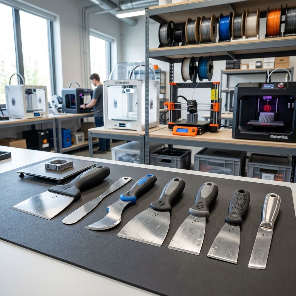
BuildTak Spatula Tool Review: Pros, Cons & Field Reality
The BuildTak Spatula uses a thin, beveled stainless steel blade designed to separate stubborn 3D prints without gouging build surfaces, offering high utility for rigid beds and engineering resins.
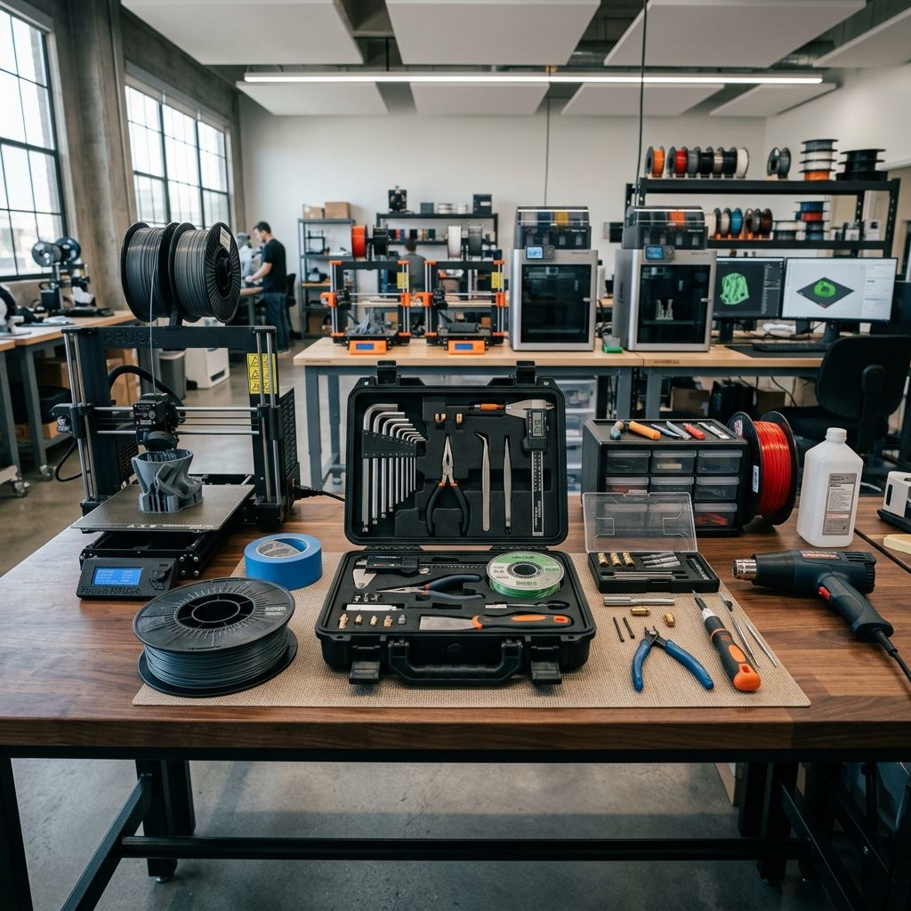
HOTO SNAPBLOQ 3-in-1 Mini Power Tool Kit Hands-On
After 150+ hours, the HOTO SNAPBLOQ has consistent motor performance but disappointing rotary runout under load. Not for precision work, but good for general light fabrication and sanding.
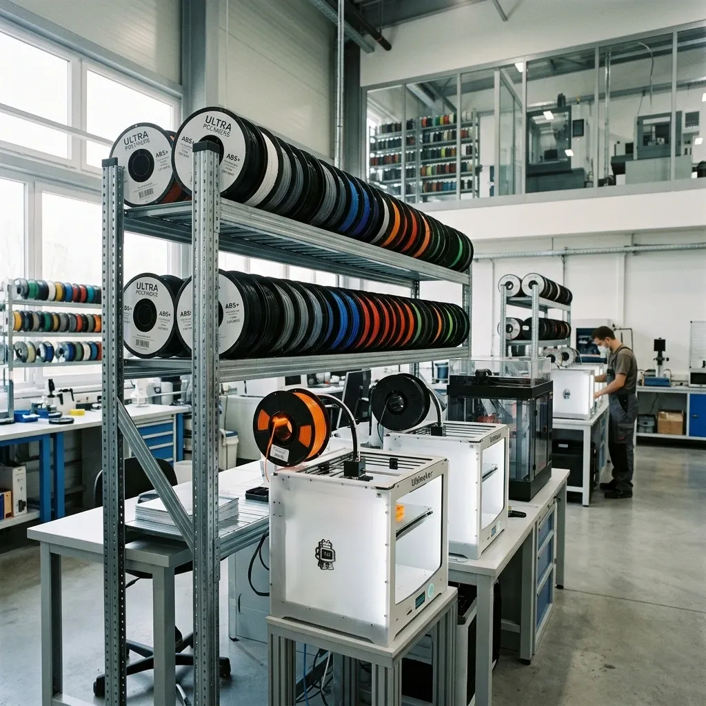
Flashforge ABS Filament Buying Guide
Flashforge ABS offers consistent diameter tolerance (±0.02 mm) and low warpage for functional prototypes and jigs. Requires heated chamber above 50°C, 245°C nozzle, 100°C bed. Best for job shops and production lines.