THSL-300-8D Lead Screw Setup and Alignment Guide

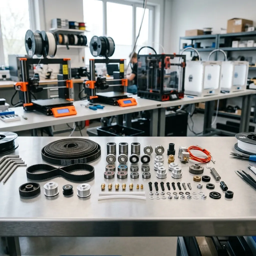
THSL-300-8D Lead Screw Installation and Mechanical Alignment
Stop fighting periodic Z-banding and gantry binding. Here is how to measure runout, decouple over-constrained kinematics, and dial in step rates on a 300 mm Tr8x8 lead screw.
Kinematic Blueprint: THSL-300-8D Mechanical Parameters
The THSL-300-8D is a 300 mm trapezoidal lead screw with an 8.00 mm nominal outer diameter and an 8.00 mm linear lead per single revolution (4-start thread with a 2.00 mm pitch). Because the lead equals 8 mm, each 360-degree rotation advances the gantry 8 mm along the Z-axis. You can calculate your exact layer height quantization with our Layer Height Calculator to match full motor step increments and eliminate microstepping rounding drift.
- Nominal Diameter: 8.00 mm (Tolerance: -0.02 / -0.05 mm)
- Pitch (p): 2.00 mm (Distance between adjacent thread peaks)
- Starts (n): 4 Starts (Multi-start trapezoidal profile)
- Lead (L): 8.00 mm/rev (Lead = Starts x Pitch)
- Helix Angle (α): ~20.0° (Non-self-locking under gravity load)
- Material Grade: 304 Austenitic Stainless Steel (Cold-rolled threads, Ra < 0.4 μm)
- Standard Nut Material: H59 Brass / POM (Polyoxymethylene Delrin)
- Straightness Limit: ≤ 0.05 mm radial runout over 300 mm span
Unboxing Inspection: Measuring Radial Runout and Thread Pitch
Before bolting any lead screw into an industrial 3D printer or desktop CNC chassis, you have to verify its dimensional integrity. The reality of workshop logistics is that 300 mm stainless rods frequently get dropped, bent, or compressed in transit. A lead screw that arrives with 0.15 mm of center runout will permanently imprint an 8.0 mm sinusoidal wave into your vertical print surfaces, regardless of how much money you spend on closed-loop stepper motors or linear rails.
To inspect the THSL-300-8D properly, place the screw on a matched pair of precision ground V-blocks positioned 20 mm in from each end on a granite surface plate. Mount a dial test indicator (DTI) with 0.01 mm graduations at the longitudinal midpoint (150 mm) so the stylus rests against the crest of the rolled thread. Slowly rotate the rod by hand through 360 degrees and record the total indicator reading (TIR).
- TIR < 0.03 mm: Precision grade. Ready for direct installation in high-resolution motion systems.
- TIR 0.03 mm - 0.07 mm: Standard acceptable shop tolerance. Must be paired with a decoupled Oldham coupler.
- TIR 0.08 mm - 0.15 mm: Marginal. Will cause visible layer stacking defects unless mounted with an unrestricted floating top.
- TIR > 0.15 mm: Reject or straighten on a manual arbor press using three-point brass v-anvils.
Next, verify the thread geometry using a metric thread pitch gauge. A common point of confusion in maintenance shops is mistaking the pitch for the lead. On a standard metric trapezoidal screw (DIN 103), the pitch is the physical distance between adjacent thread peaks—2.00 mm on the THSL-300-8D. However, because this rod is cut with four independent interleaved helix starts, the actual linear advance per complete turn (the lead) is 4 × 2.00 mm = 8.00 mm. If you mistakenly configure your motion controller for a 2.0 mm single-start screw, your machine will over-extrude vertical travel by a factor of four, driving your gantry directly into the mechanical endstops.
Physics of Z-Axis Wobble: Over-Constrained Kinematic Chains
The single most destructive installation mistake technicians make with the THSL-300-8D is over-constraining the kinematic assembly. In an ideal mathematical model, the stepper motor shaft, the flexible coupler, the lead screw, the brass nut, and the top bearing all share a single, perfectly collinear rotational axis. In the real physical world, every machined component has positional tolerances, runout, and thermal expansion coefficients.
When you clamp the bottom of the lead screw rigidly to the motor shaft and simultaneously clamp the top of the rod into a rigid KP08 pillow block bearing, you eliminate all rotational and translational degrees of freedom. If the lead screw has even 0.05 mm of residual bow, or if the motor mount is tilted by just 0.5 degrees relative to the vertical linear guide rails, the screw acts as an eccentric cam. As it rotates, it exerts a cyclic bending moment into the linear carriage.
The lateral deflection force transmitted into the X-gantry brass nut bracket can be modeled using the beam deflection equation for a beam with both ends fixed subject to angular eccentricity offset e:
F_lateral(z) = (12 × E × I × e) / ((L - z)² × z²)
Where E is the Young's modulus of 304 stainless steel (193 GPa), I is the second moment of area of the screw core (I = π × d_root&sup4; / 64 with d_root ≈ 5.5 mm), e is the centerline misalignment offset, L is the 300 mm length, and z is the current vertical position of the gantry. Notice how the lateral force spikes exponentially as the gantry approaches the constrained ends (z → 0 and z → L). This lateral thrust overwhelms the stiffness of V-slot wheels or linear guide carriages, deflecting the nozzle by 0.02 mm to 0.06 mm in the XY-plane and creating visible periodic Z-banding at 8.0 mm layer intervals.
The engineering solution is straightforward: let the top end of the THSL-300-8D float free, or mount the top bearing in an oversized housing with compliant silicone dampening rings that allow ±1.0 mm of radial float while preventing rod whip during high-speed rapids.
Coupler Mechanics: Eliminating Hysteresis and Spring Effects
The interface between the NEMA 17 stepper motor shaft (5.00 mm diameter) and the THSL-300-8D lead screw (8.00 mm diameter) determines whether your motion commands translate into rigid mechanical displacement or springy hysteresis. Cheap spiral-cut (helical beam) aluminum couplers are widely sold with DIY kits, but they represent a terrible design compromise for vertical positioning axes.
A helical beam coupler is essentially an axial spring with high torsional compliance. When your slicer commands a rapid 0.4 mm Z-hop or high acceleration retraction, the mass of the gantry (1.5 kg to 3.5 kg) causes the spiral slits in the coupler to compress and expand dynamically. This axial elasticity produces settling oscillations and micro-layer height errors, compounding acceleration dynamics similar to those explored in Fixing Layer Shift in Simplify3D: Acceleration Settings.
| Coupler Architecture | Axial Stiffness (N/μm) | Radial Compliance (mm) | Torsional Backlash | Recommended Field Application |
|---|---|---|---|---|
| Helical Beam (Slit Aluminum) | Low (Springy: 12-25 N/μm) | High (±0.5 mm) | Zero | Rotary encoders only; avoid on vertical Z-drives |
| Rigid Set-Screw / Solid Clamp | Infinite (Rigid) | Zero (Rigid) | Zero | Perfect linear setups; causes severe Z-banding if runout exists |
| Oldham Three-Piece Coupler | High (> 280 N/μm) | High (±0.4 mm float) | Near Zero (< 0.02 mm) | Standard choice for Cartesian 3D printers and lead screw retrofits |
| Curved Jaw / Plum Elastomer | Medium-High (180 N/μm) | Moderate (±0.2 mm) | Zero (Preloaded) | Good vibration damping on dual-driven Z-axis gantries |
For workshop retrofits, an Oldham coupler with a brass or acetal sliding center disk is the superior choice. The three-piece Oldham design allows the input and output hubs to slide laterally along orthogonal keyways, isolating radial motor runout from the lead screw without sacrificing axial rigidity or introducing rotational backlash.
Step Rate Calculation and Layer Height Quantization
Configuring the firmware steps per millimeter for a THSL-300-8D requires precise mathematical calculation based on motor step angle, driver microstepping, and the 8.00 mm thread lead. Never guess or tune this value with calipers over a 20 mm printed cube; calibrate it analytically from the mechanical pitch.
The standard formula for lead screw linear step resolution is:
Steps_per_mm = (N_steps × M) / Lead
Where:
- N_steps: Native motor full steps per revolution (200 for a standard 1.8° stepper; 400 for a precision 0.9° stepper)
- M: Microstepping factor configured in stepper driver firmware (typically 16x, 32x, or 64x)
- Lead: Linear lead per revolution (8.00 mm for THSL-300-8D)
For a standard 1.8° stepper motor running at 16x microstepping:
Steps_per_mm = (200 × 16) / 8.00 mm = 3200 / 8.00 = 400.00 steps/mm
If you upgrade to a 0.9° stepper motor at 16x microstepping:
Steps_per_mm = (400 × 16) / 8.00 mm = 6400 / 8.00 = 800.00 steps/mm
The Physics of Full-Step Layer Quantization
While modern stepper drivers (such as TMC2209 or TMC5160) interpolate up to 256 microsteps for silent operation, microstepping cannot deliver full holding torque between magnetic pole positions. The holding torque at an intermediate microstep angle degrades according to:
T_hold(θ_m) = T_nominal × sin(90° / M)
At 1/16 microstepping, a single microstep holds only about 9.8% of the motor's full-step torque. If the gantry stops on a fractional microstep position, gravitational load and mechanical seal friction can cause the rotor to settle onto the nearest full magnetic pole detent. To prevent microstep drift and inconsistent layer heights, you must quantize your slicer layer heights to full-step mechanical increments (often called 'magic numbers').
The fundamental full-step mechanical resolution of the THSL-300-8D with a 1.8° stepper is:
Full_Step_Resolution = Lead / N_steps = 8.00 mm / 200 = 0.04 mm
Always slice your models in exact multiples of 0.04 mm (e.g., 0.08 mm, 0.12 mm, 0.16 mm, 0.20 mm, 0.24 mm, 0.28 mm). Choosing an arbitrary layer height like 0.15 mm forces the motor to alternate between full steps and unstable microsteps every layer, causing subtle surface banding similar to the mechanical balance issues analyzed in Common Prusa MK4/S Problems and Fixes.
Anti-Backlash Nut Tuning: Spring Preload vs Friction Drag
Standard solid brass nuts have a built-in radial and axial clearance of 0.03 mm to 0.08 mm to prevent binding when temperature fluctuates. While this backlash is partially masked on vertical 3D printers by the downward gravitational pull of the gantry, bidirectional motions (such as adaptive layer probing, auto bed leveling mesh compensation, and fast Z-hops) expose backlash as vertical positioning error.
A two-piece spring-loaded anti-backlash nut eliminates axial play by using a compression spring to push two threaded nut halves in opposite directions against the upper and lower flanks of the trapezoidal thread. However, setting the correct spring preload is a delicate engineering tradeoff.
The dynamic axial load equation required to prevent backlash separation during rapid downward acceleration is:
F_spring ≥ m_gantry × (g + a_z,max) + F_drag
Where m_gantry is gantry mass (2.0 kg), g = 9.81 m/s², a_z,max is peak downward acceleration (1.5 m/s²), and F_drag is linear guide seal friction. For a 2.0 kg gantry, the spring force must exceed 22.6 N.
If you over-compress the spring to maximize rigidity, you increase the normal force on the thread flanks, which spikes the frictional driving torque required by the stepper motor according to the power screw torque equation:
T_drive = (F_axial × d_mean / 2) × [ (tan(α) + μ × sec(θ)) / (1 - μ × tan(α) × sec(θ)) ]
Where d_mean ≈ 7.00 mm is the mean pitch diameter, α ≈ 20.0° is the lead angle, θ = 15.0° is the trapezoidal thread half-angle (30° included angle), and μ is the coefficient of kinetic friction (0.18 - 0.25 for dry brass on 304 stainless). Excessive spring preload will double the driving torque, overheating your NEMA 17 motor and causing random skipped steps during travel.
For workshop machines, consider upgrading from brass to POM (Delrin) anti-backlash nuts. POM features a lower friction coefficient (μ ≈ 0.12), zero stick-slip jerk, superior acoustic dampening, and natural compliance that tolerates minor lead screw straightness imperfections.
Tribology and Lubrication: What to Apply and What to Ban
Trapezoidal threads operate on sliding surface contact rather than rolling contact (unlike ball screws). This makes tribology and lubricant film thickness critical to the longevity of the THSL-300-8D.
The workshop floor is full of terrible lubrication practices. The worst offender is WD-40 Multi-Use Product; it is a solvent and water-displacer, not a persistent lubricant. Spraying WD-40 onto a brass lead screw nut washes away existing grease, dissolves plastic components, and leaves a sticky varnish that attracts abrasive filament dust and airborne wood particles. Similarly, thin mineral oils (sewing machine oil) drip off vertical 300 mm screws within 48 hours of operation.
- Synthetic PTFE Grease (NLGI Grade 2): The gold standard for open lead screws (e.g., Super Lube Synthetic Grease with Syncolon PTFE). Forms a durable boundary lubrication film that resists wiping action and dampens harmonic vibration.
- Dry MoS2 (Molybdenum Disulfide) Spray: Best choice for dusty environments (woodshops, carbon-fiber composite printing). Dries to a solid micro-film that provides low friction without attracting airborne particulate debris.
- White Lithium Grease (NLGI Grade 1): Acceptable budget alternative for clean enclosed printer frames; requires reapplication every 250 operating hours.
- Banned Substances: WD-40, silicone spray (insufficient film strength under high localized contact pressure), motor oil, and automotive wheel bearing grease (too viscous, causes excessive motor drag at room temperature).
Step-by-Step Installation Protocol: From Bare Motor to Paralleled Rails
Follow this exact shop-floor procedure to install and align the THSL-300-8D without introducing mechanical binding or kinematic over-constraint:
Step 1: Frame and Motor Mount Squaring. Check that the stepper motor mounting bracket is perpendicular to the vertical linear guide rails using a precision engineer's square. If the motor face tilts forward or backward, place 0.1 mm brass shim stock under the low mounting lugs.
Step 2: Oldham Coupler Staging. Slide the bottom hub of the Oldham coupler onto the motor shaft. Ensure a 1.0 mm air gap exists between the top of the motor boss and the bottom of the coupler hub so the coupler does not rub against the motor bearing shield. Tighten the lower clamping screw to 1.2 N·m.
Step 3: Lead Screw Insertion and Axial Clearance. Lower the bottom end of the THSL-300-8D into the upper hub of the Oldham coupler. Ensure the bottom of the lead screw does not bottom out against the top of the motor shaft inside the coupler. Leaving a 2.0 mm internal axial gap allows the elastomer or center disk to absorb axial vibrations and thermal expansion. Torque the upper clamping screw to 1.2 N·m.
Step 4: Threading the Nut and Loose Flange Mounting. Thread the brass or POM anti-backlash nut onto the screw from the top. Lower the X-gantry carriage over the screw and loosely fasten the nut mounting screws into the gantry bracket. Leave the mounting screws half a turn loose so the nut can float radially.
Step 5: Full-Stroke Alignment Sweep. Move the gantry carriage manually to the very bottom of the Z-axis (Z = 0 mm). Tighten the motor mount screws. Now slowly traverse the gantry by hand to the top of the stroke (Z = 280 mm). Because the nut is loosely mounted, it will self-align along the true rotational axis of the screw without binding. If you encounter any stiff spots or increased resistance, use our 3D Printer Troubleshooting tool to isolate structural frame racking from lead screw runout.
Step 6: Final Nut Clamping Under Dynamic Travel. While holding the gantry at mid-stroke (Z = 150 mm) where lateral binding is minimized, gently snug the nut bracket screws in a criss-cross diagonal pattern to 0.8 N·m.
Step 7: Firmware Validation and Resonance Sweeps. Flash your 400.00 steps/mm configuration to the mainboard. Command a slow 5 mm/s jog across the entire 300 mm span while monitoring motor current and acoustic hum. If high-speed travel induces frame resonance, verify your input shaping frequencies as outlined in Fixing Klipper Input Shaper Resonance Issues.
Field Diagnostic and Troubleshooting Matrix
When vertical motion issues appear during production, use this matrix to pinpoint the mechanical root cause before replacing parts blindly:
- Symptom: Repeating horizontal ribs across vertical walls at exact 8.0 mm spacing.
Root Cause: Lead screw radial runout (TIR > 0.08 mm) or eccentric coupler clamping transferring lateral wobble into the gantry.
Action: Install an Oldham floating coupler, loosen any rigid top pillow block bearings, or replace bent lead screw. - Symptom: Gantry slides down under its own weight when stepper motors are de-energized.
Root Cause: Normal physical behavior for 4-start screws. The 20-degree helix angle exceeds the static friction angle, making the THSL-300-8D non-self-locking.
Action: Add a software park macro before motor power-down, install a mechanical counterweight, or use a 2-start 4 mm lead screw if passive self-locking is mandatory. - Symptom: High-pitched screeching or squeaking during rapid vertical travel.
Root Cause: Boundary lubrication failure causing dry metal-on-metal galling between 304 stainless steel and H59 brass.
Action: Clean screw thoroughly with 99% Isopropyl Alcohol, inspect brass threads for swarf, and apply NLGI-2 PTFE synthetic grease. - Symptom: Stepper motor skips steps or stalls when gantry approaches Z = 0 mm.
Root Cause: Angular misalignment between motor shaft and vertical guide rails, pinching the lead screw at the bottom of its stroke.
Action: Loosen motor bracket screws, shim the motor base to restore 90-degree alignment with guide rails, and re-torque at Z = 5 mm. - Symptom: First layer thickness changes unpredictably between consecutive print jobs.
Root Cause: Axial play inside worn brass nut or axial expansion/contraction in an elastic helical beam coupler during Z-homing.
Action: Replace worn nut with a preloaded POM anti-backlash nut and swap helical coupler for a rigid-axial Oldham coupler.
Frequently Asked Questions
What is the difference between pitch and lead on the THSL-300-8D lead screw?
Pitch is the 2.0 mm distance between individual adjacent thread crests, whereas lead is the 8.0 mm linear advance the nut travels during one full 360-degree rotation across the 4 interleaved thread starts.
Should I install a top pillow block bearing to secure the upper end of the THSL-300-8D?
No, constraining the top end creates an over-constrained kinematic chain that forces any slight screw runout directly into the print carriage as periodic Z-banding; always leave the upper end free or floating.
Why does my 3D printer gantry drop by itself when the motors power off?
The 8.0 mm lead creates a steep 20-degree helix angle that exceeds the friction angle of steel on brass, making the THSL-300-8D non-self-locking under the gravitational mass of the gantry.
What firmware step rate should I configure for a THSL-300-8D with a standard 1.8° stepper motor?
At standard 1/16 microstepping, configure exactly 400.00 steps per millimeter in your firmware, calculated as 200 full steps per revolution multiplied by 16 microsteps and divided by the 8.00 mm lead.
Critical Alignment Rule: Never Hard-Clamp the Top Bearing
If your machine frame includes a top bearing bracket for the Z-axis, remove the radial grub screws or ream the mounting bore to allow at least 1.0 mm of unrestricted lateral float. Clamping an 8 mm rolled stainless rod into concentricity at both the motor coupler and the top frame will guarantee visible layer stacking errors. Always verify smooth manual rotation across the entire 300 mm travel span before applying full motor current.
Related Intel
Replacement Timing Pulleys: A Field Guide to Belt Drive Precision
When replacing timing pulleys, focus on bore concentricity (≤0.05 mm runout), tooth flank finish (Ra≤1.6 μm), and set screw torque (1.5-2 N·m). Soft alloys and rough flanks cause premature belt wear and positional errors.
Phrozen PFA vs FEP: Real Differences for Resin Printing
Phrozen's PFA film (nFEP) has lower surface energy than FEP, reducing peel forces by 15-20%, which improves print success with high-viscosity resins. It costs 2-3x more but lasts 30-50% longer if installed with correct tension.